Components
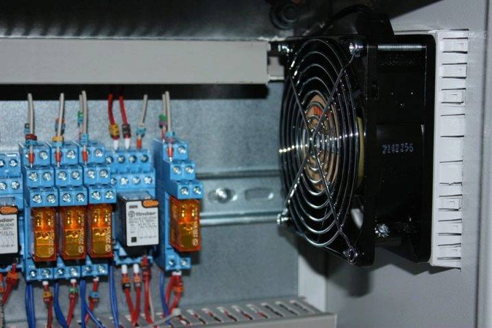
The fan control cabinet is equipped with a power supply, controllers, converters and a large number of on / off switches. The switches, in turn, are connected to electric heaters, recuperators, fans, water heaters and refrigeration units. A mandatory element of the switchboard is a manual control unit, which takes over the regulation and control functions in the event of a failure or malfunction of the automation. In addition, all cabinets are equipped with emergency alarm sensors that are triggered in the event of an emergency or pre-emergency situation.
Sensors, which are a kind of receptors and collect information about the performance of each unit, play a special role in monitoring the operation of ventilation systems. With their help, you can get a visual picture of the pollution of air flows, their temperature and humidity, as well as the speed of movement of air masses and the frequency of rotation of the fan blades. Temperature sensors are available in both digital and analog versions, and when the temperature regime inside the system changes, they help to switch the entire installation to another mode. Humidity sensors work in the same way. The information received by the sensors goes to automatic regulators, which, in turn, adjust the operation of key components of ventilation systems.
By location, the sensors are divided into external and internal. The former are often called atmospheric and are installed on the outside of buildings. Internal, in turn, are subdivided into channel and surface models. Channel ducts are installed inside the air ducts on the walls or across the movement of air masses. Surface are placed on the surface of the nodes and carry out the removal of parameters from these devices.
Controllers are an equally important element of control cabinets. The devices receive information from the sensors and process it automatically. After processing the parameters, the controllers send a signal to the main units of the ventilation units, such as fans, air heaters, refrigeration units, after which they change their operating mode. Functionally, the controller can either serve several devices, or interact with only one of them. Versatile models are often equipped with microprocessors, which makes them less bulky and easy to fit in a small cabinet or stand.
Another element of the shields configuration is the fan blade speed converters. Thanks to these devices, it is possible to regulate the number of engine revolutions, thereby significantly reducing the amount of electricity consumed by the installation. In addition to cost savings, this leads to a significant reduction in the wear of the fan parts and extends the overall life of the air handling unit.
We connect a fan without a timer
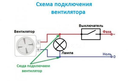
To connect a fan in the toilet, the simplest scheme of simultaneously turning on the fan with lighting in the bathroom is suitable. Zero and ground from the junction box are connected directly, and the phase from the same twist after the switch from which the phase wire goes to the lamp in the toilet. It is possible to connect a fan in parallel with the lamp in the bathroom. To do this, we simply take from it the phase, zero ground for connecting the fan.
According to this scheme, simultaneously with turning on the lamp, the fan will start and work. But such a scheme is not very convenient, because after turning off the light, the fan stops working, without having time to remove unpleasant odors. I recommend using the second scheme.
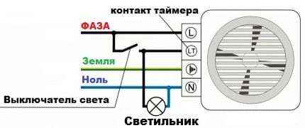
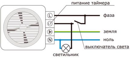
Timed fans are more expensive, but they are great for use in the bathroom. Switching on occurs together with the lighting, and switching off separately from it with a time delay, the value of which is adjustable. The fan will work in the bathroom and remove moisture even after you leave, and will turn off automatically after a set period of time.
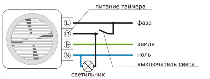
To connect a fan with a timer, you need 4 wires. A direct phase comes to the L- contact from the junction box, to the Lt- phase through the light switch. To N- zero, and the grounding conductor is connected to the contact with the grounding designation.
This connection option is considered the simplest from a technical point of view. The switch is placed in front of the entrance to the bathroom or indoors. It is advisable to install it away from plumbing equipment, where splashes on the electrical contacts are excluded.
We suggest that you familiarize yourself with How to drain water from Ariston
Plastic axial fans do not have a terminal outlet for connecting the ground loop. Everything is limited to phase switching with a zero core. Connections are organized in a distribution board or socket with a depth of up to 60 mm.
This is the most common connection option.
You will need to perform the following wire commutation:
- the zero conductors of the ventilation unit and the electrical network are connected and insulated;
- the exhaust and switch phases are paired in the same way;
- a phase conductor of the mains is connected to the input terminal of the switch.
An important condition is the connection of the ground loop.
It is convenient when the ventilation unit starts up at the same time as the lighting devices are turned on. The most practical option is to be combined with a two- or three-button switch. A socket box is installed in the corresponding hole. Electrical switching is performed in it.
The input terminal is connected to the phase conductor of the supply network. The output contact closes to a phase of the air conditioner. After connection, it is necessary to check the reliability of the connection and the integrity of the insulation. Then the working mechanism is fixed in the socket box and the cover with the keys is installed.
The units equipped with a timer are easy to use.
The principle of operation of such a device is as follows:
- The fan starts up in parallel with the lighting.
- After turning off the lamp, the unit rotates for a user-specified time, removing exhaust air from the room.
- Then it automatically shuts down.
To ensure the full functioning of the device, 4 cores are used:
- phase from the switchboard;
- an electrical wire connected to a light bulb;
- ground loop;
- zero core;
For self-installation, it is recommended to purchase a surface-mounted device with the necessary set of built-in sensors - humidity, motion, etc.
You can turn on the lighting and ventilation with one button, but with a slight delay in starting the climate unit. Some models are equipped with an electronic timer. In such devices, it is possible to select a functional mode. Their switch is implemented as 3 pin contacts. Two of them are closed with a jumper - a special jumper. One mode is called "toilet". To activate it, the upper and middle contacts are closed.
The meaning of this mode is that when power is applied, the engine of the ventilation unit starts immediately.The second mode is called "bathroom". The light comes on immediately after pressing the switch key, and the cooler starts working with a set delay. In this mode, the unit will start up only if the time interval between turning on and off the lighting is at least 90 seconds.
When the hood is connected to a two-button switch, a phase is interrupted at one of the contacts. This method of electrical switching allows ventilation and lighting to be switched on separately. The neutral and phase conductors of the power supply system are closed at the corresponding outputs of the device terminal block. On one of the keys of the switch there is a control phase. It is closed to the exhaust timer contact.
The unit is controlled and the operating mode is configured through it. This wire is color coded in brown. You can use the green-yellow conductor that is not used with this type of connection, which is responsible for grounding. In this case, it will not start on the cooler. It is recommended to use a three-core power cable to connect the hood to a two-button switch. This will allow the lighting and ventilation to function separately or in tandem.
General information
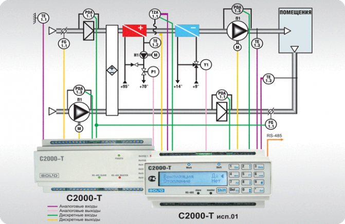
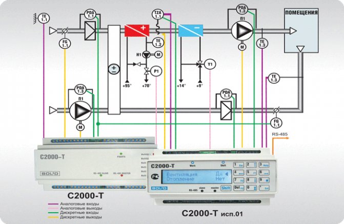
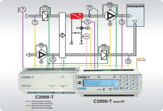
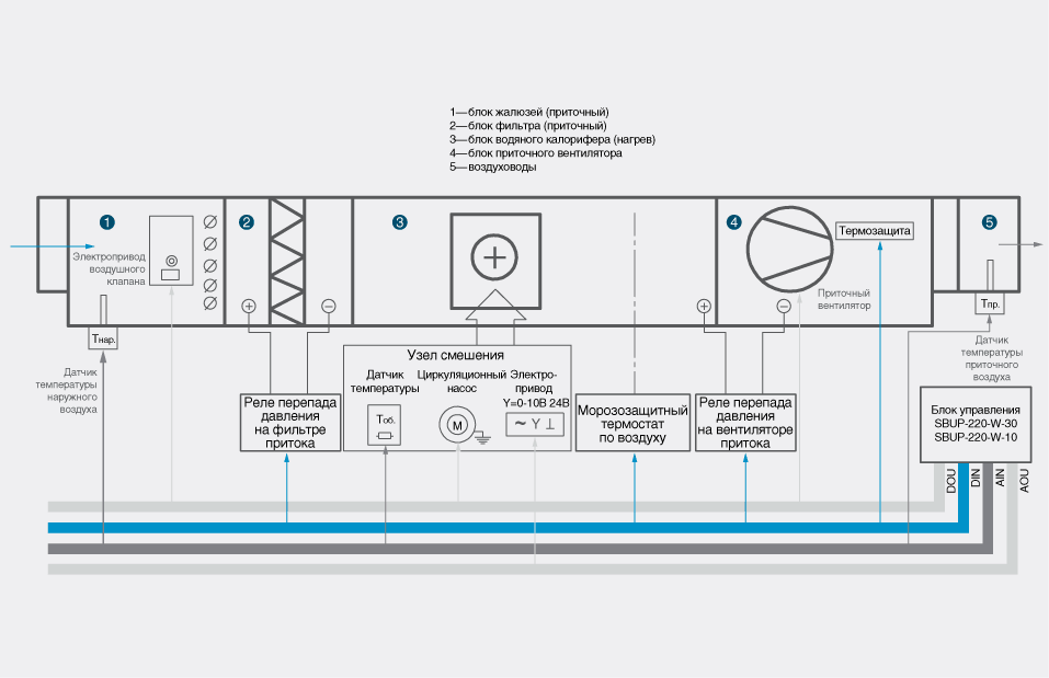
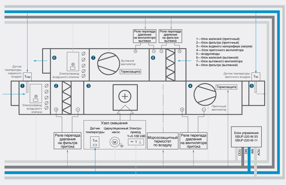
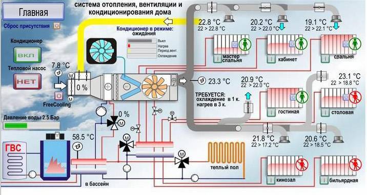
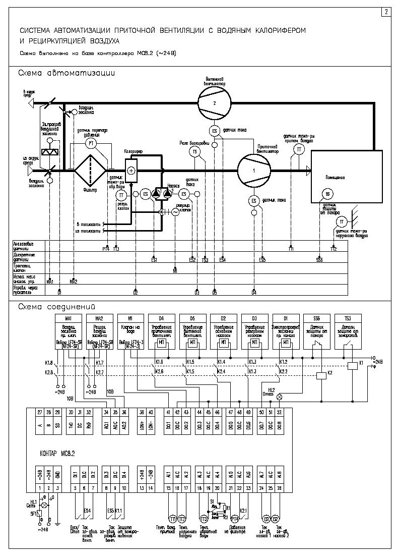
ACS ventilation is designed to control and manage supply and supply and exhaust ventilation systems of buildings with a different set of equipment, which may include: recuperator, cooler, air heater, control valves and pumps in the cooler and heater circuit, air dampers, filters.
Tasks to be solved when introducing ACS:
- automatic maintenance of the set temperature and air exchange rate in the manned room;
- ensuring fire safety - control of fire-retarding valves;
- timely diagnostics of ventilation equipment failures.
- maintaining the air temperature in the serviced premises within the limits set by the controller program;
- continuous automatic protection of the water heat exchanger against freezing by water temperature and supply air temperature, control of air filter contamination in the supply system;
- operation of ventilation systems in the "Day" / "Night" and "Winter" / "Summer" modes;
- monitoring the state of the controlled equipment.
ACS ventilation exchanges information with the dispatching console, providing the following capabilities:
- transmission to the dispatching console of technological parameters, messages on emergency situations and data on the operation of executive mechanisms;
- remote control for individual mechanisms, if necessary, while maintaining automatic control for the system as a whole, and incorrect operator actions are blocked;
- receiving from the dispatching console commands for unscheduled switching on and off, as well as assignments for the temperature in the serviced premises.
In addition to the main control mode from the dispatching console, the ventilation systems can be controlled locally from the push-button control stations (KPU) located in the serviced premises.
The hardware and software platform of the ACS provides high flexibility in configuration and programming. As a result, the following characteristics of the ACS are provided, which distinguish it from similar products:
- the ability to connect small ventilation systems to controllers of large ventilation systems without installing additional control cabinets;
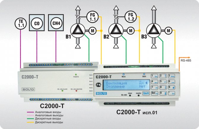
- the ability to connect the actuators of other engineering systems (fire protection valves, smoke exhaust fans, pumps, SPS, etc.) to the controllers of ventilation units;
- the possibility of implementing modifications to the controller and control programs in a short time and at low cost in the event of changes in the original project of automation of engineering systems;
- flexibility of control algorithms, which makes it easy to modify them during the design of engineering systems in the event of the appearance of the corresponding customer requirements;
- the ability to transfer information to the upper level using any standard protocols requested by the supplier of the dispatching system.
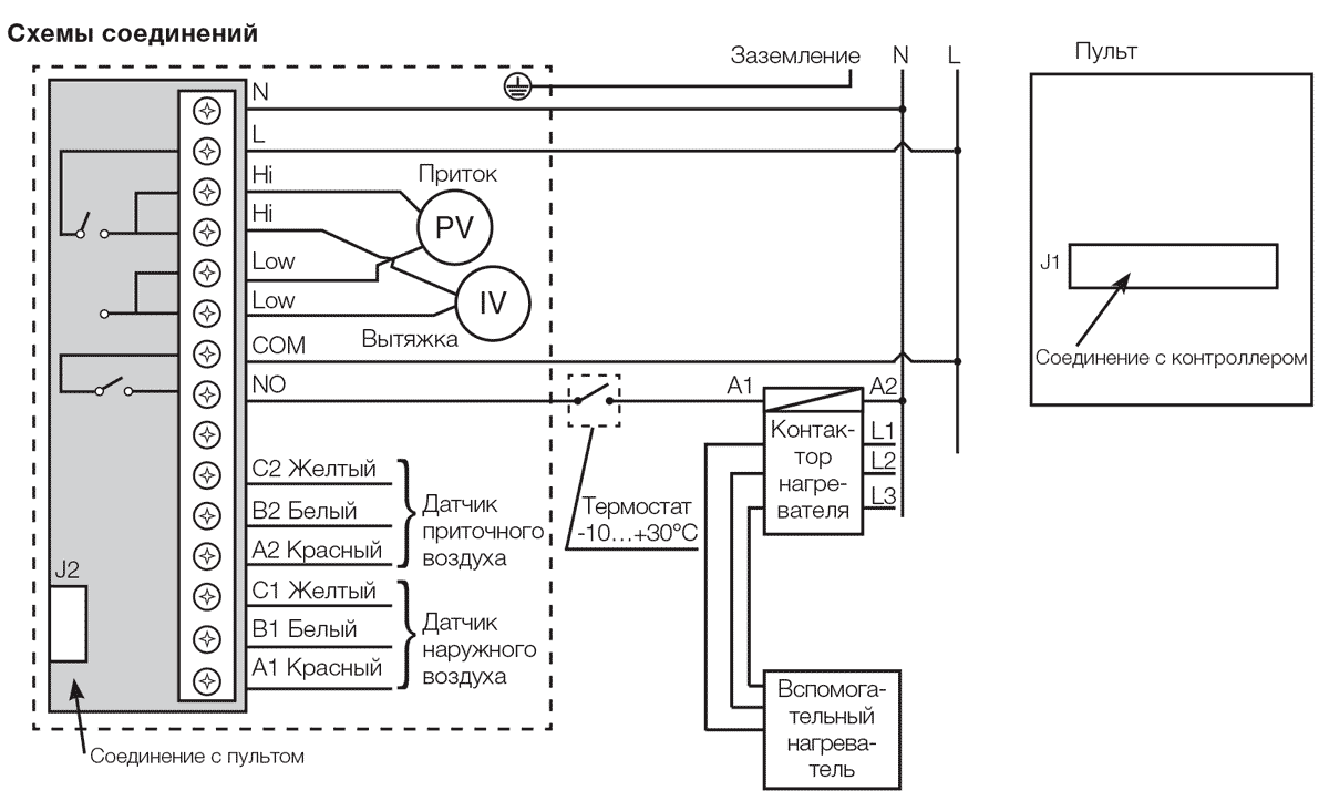
Automation panels
The operation of an automated system, its convenience, reliability and safety of operation directly depend on the process control algorithms (specialists who performed the design and commissioning), as well as on the capabilities of the components. The algorithms are implemented at the software level and are "sewn" into freely programmable controllers installed in automation panels.
When connecting sensors to the automation panel, the type of signal transmitted by the converter (analog, discrete or threshold) is taken into account. Expansion modules that control device drives are selected in the same way.
The ventilation system shields are power, control or combined, if the system is small. Automation panels for ventilation provide:
- Turning on and off the ventilation system;
- Equipment status indication;
- Protection against incorrect connection of the supply voltage and short circuit;
- Air handling unit performance management;
- Air filter status indication;
- Protection against overheating of electric motors;
- Frost protection for the air heater;
- Maintenance and control of the air temperature at the inlet of the ventilation unit and in the room;
- Possibility of using temporary manual control algorithms.
Device diagram
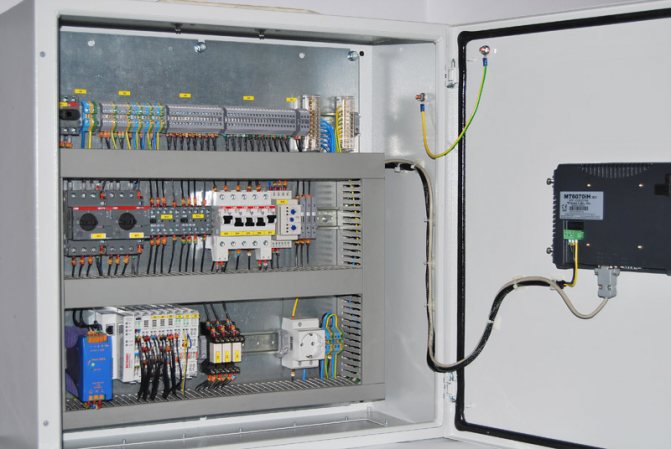
Connection of control cabinets is carried out according to the standard scheme and is regulated by GOST R51321-1. Cabinets, stands and panels are installed in corridors, panel rooms or utility rooms. In the presence of technical conditions, ventilation and fire control units are located in one cabinet, which is placed in the control room. This will provide quick access to the emergency and work ventilation control panels and allow quicker response to system problems.
The rooms in which the boards are installed have special requirements for the level of humidity and temperature. Devices must be reliably protected from direct ultraviolet rays, water drops and dust. Magnetic vibrations and radio interference can also negatively affect the correct operation of the devices, therefore their influence on the devices should be limited. The temperature range at which the operation of control cabinets is allowed is from -10 to +55 degrees. Installation of the device requires mandatory grounding, and the frequency of the mains current should not exceed 50 Hz. As a power source, 220 and 380 V power grids are used.
The main requirements of the layout are to find all control devices on the same stand and in the same plane. The most important units responsible for the safety of the device must be equipped with light indicators and preferably connected to a personal computer. In addition, the devices responsible for the correct operation of the main units must be equipped with two types of control: manual and automatic. The most convenient for use are cabinets equipped with a remote control, which allow a person who does not have much experience in ventilation control to monitor its operation. In addition, the device connection diagram should be simple and extremely easy to understand. This will help in the event of an emergency to turn off the unit yourself, without waiting for the arrival of repair services.
Calculation of ventilation systems
The calculation of the ventilation of the room at the first stage requires the correct choice of equipment, which will have the necessary performance characteristics in terms of the amount of blown air (cubic meter / hour).
It is also considered very important to consider such a parameter as the frequency of air exchange. It characterizes the number of complete air changes within one hour inside the building.
In order to correctly determine this parameter, it is necessary to take into account the norms and rules of construction. The multiplicity depends on the purpose of using the premises, what is in it, how many people, etc.
The calculation of ventilation of industrial premises for this indicator also involves accounting for equipment, as well as the characteristics of its operation and the amount of heat or moisture that it emits. For premises intended for human living, the air exchange rate is 1, and for industrial premises up to 3.
Conciseness measures form a performance value, which can be as follows:
- from 100 to 800 m³ / h (apartment);
- from 1000 to 2000 m³ / h (house);
- from 1000-10000 m³ / h (office).
Also, it is necessary to correctly design and install air distributors. These include special air diffusers, air ducts, bends, adapters, and so on.
Providing reliable and correct ventilation is an extremely important and necessary system in any building.
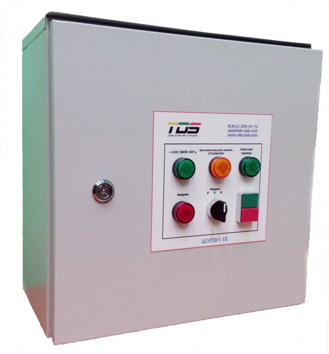
What is SHCHUV for, where is it used
Small household ventilation systems used in multi-storey buildings and the private sector do not require any additional appliances. They are controlled remotely, using a remote control, or manually.
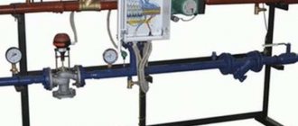
Unlike household systems, industrial systems are distinguished by a significantly longer network length. Many functional devices, primarily fans, are initially installed in hard-to-reach places. Due to limited access, control is carried out using a unit equipped with a whole set of special equipment.
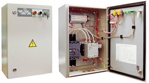
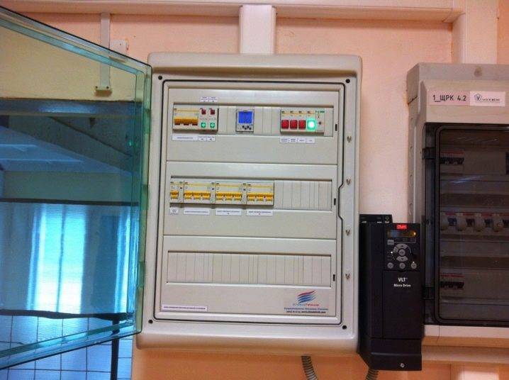
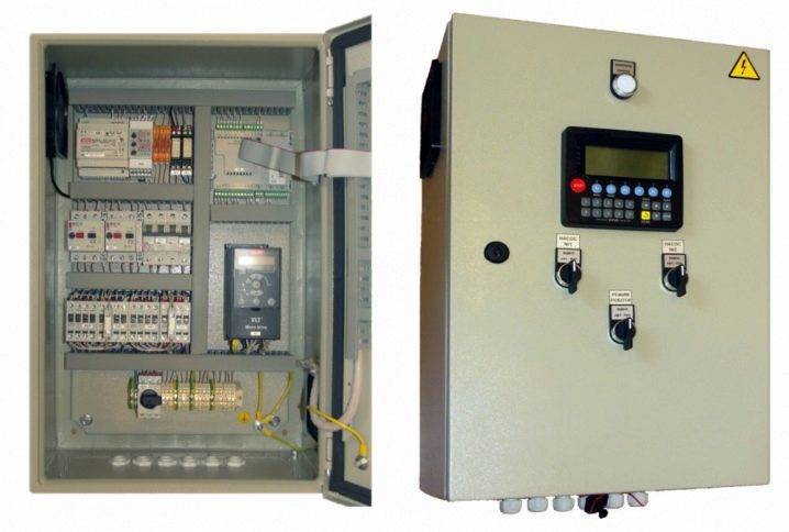
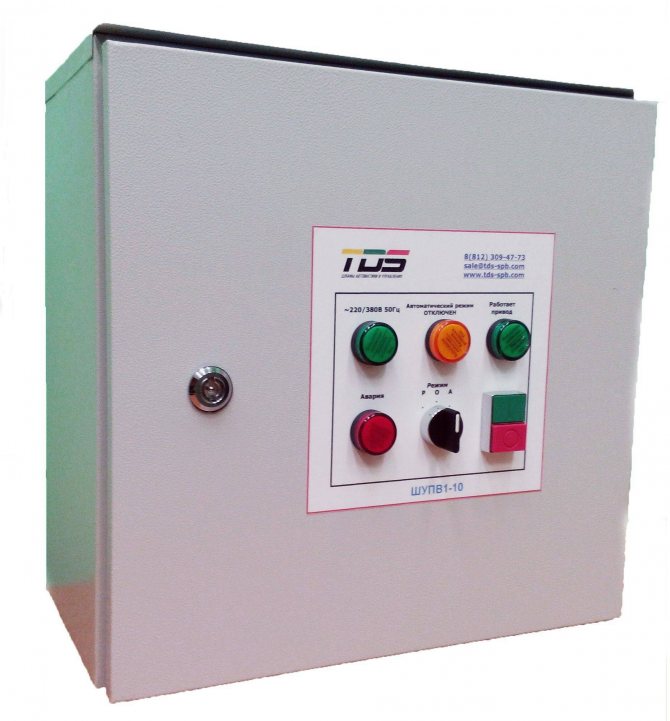
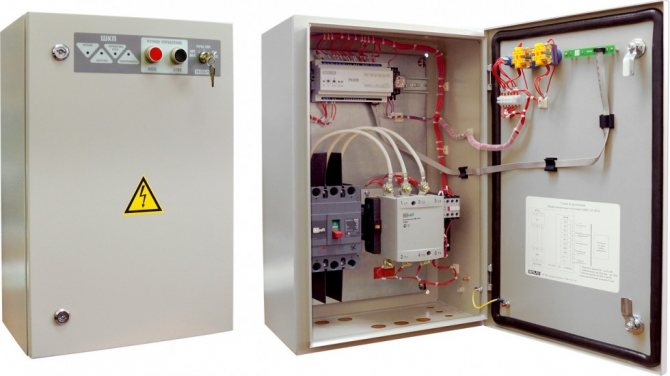
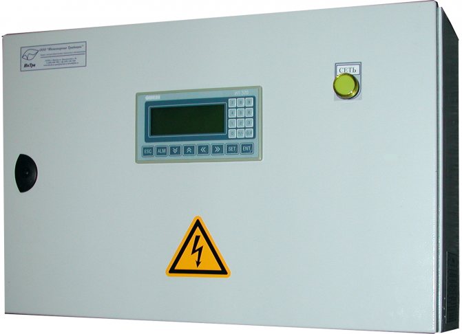
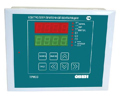
The modern ventilation control panel - SHCHUV is manufactured in the form of a panel on which the adjusting indicator devices are located, as well as in the form of metal cabinets fixed to the wall or installed on the floor. The inner space with the equipment located here is protected by hinged doors. To restrict the access of unauthorized persons, they are locked.
The main tasks that the ventilation control panel solves are as follows:
- Control over equipment, devices and equipment that are part of ventilation systems.
- Protection of controlled devices in the event of emergency situations caused by overheating, improper installation and connection, short circuits.
- Adjustment functions - setting the required parameters for the performance and power of the equipment.
- The ability to program individual components and assemblies or the entire system for a specific period, from 1 day to 1 month.
- The control and adjustment processes of the ventilation control panel are greatly facilitated by the installed display.
- Each of the rooms can maintain its own temperature, which can be changed at the right time.
- The air filters are monitored, the degree of their pollution, as well as the condition of the inner walls of the air ducts.
- Control over the operation of seasonal equipment, which is exposed to negative influences due to sudden changes in outdoor temperature.
The control panel of the ventilation system installed at the facility allows, being in one place, to constantly monitor the work processes and the condition of all equipment. In the event of a breakdown or stop of some devices, timely detect and eliminate them.
Functions of automatic ventilation cabinet
Thanks to the improvement of equipment in the field of ventilation automation, it became possible to exclude the human factor from the operation of the ventilation control cabinet. Automation guarantees a high level of safety of the huge functionality that ventilation controlled by the cabinet actuators possesses.
A wide range of ventilation control cabinets include:
- Connection of any ventilation elements with different physical characteristics and different ports for installing the system.
- Ability to monitor mains voltage.
- Control of special electric valves to ensure uninterrupted power in the mains. Increases the operation of devices, excluding their overheating, short circuit, overload.
- Control of the set parameters for the room and the fan speed.
Standard functions
A conventional ventilation control cabinet has the following functions:
- Control of the heating temperature of a single element of the ventilation system.
- Control over the parameters of the air valve actuator.
- Monitoring the cleanliness of air filters. In case of contamination, an audible signal is sent to the ventilation equipment control unit.
- Control of a valve for moving air masses to maintain the set air temperature in the room.
- The ventilation equipment unit is controlled manually, switching on and off.
- Elimination of overheating and short circuit of the pump motor.
- With the help of light indicators, you can get information about the operation of the system as a whole.
- Possibility of extending the stopping time of movement: both supply and exhaust air, by SHUV fans (ventilation control cabinet).
- Maintaining a log of failures in the operation of the forced ventilation system.
- Control over icing of parts of freon coolers.

Advanced functions
The set of advanced functions depends on the specific model of the ShUV device. Functions such as are often used:
- Control of special valves to regulate the pressure in the event of a fan belt break.
- Automatic control over the amount of carbon dioxide.
- Saving all work data in logs after a power outage.
- Control over a special chamber for mixing air flows.
- Programming a week ahead of the entire workflow.
- Monitoring the parameters of the cooling valve.
- Control by means of an electric heater.
- Using the remote control.
- Implementation of effective work with sensors designed to control various parameters of a room using a cascade method.

Purpose of ventilation control cabinets
Today the ventilation control cabinet is an integral part of the air exchange system. It greatly facilitates the operation of equipment for providing fresh air to the premises or utilizing waste gases.
We recommend that you familiarize yourself with: Industrial ventilation
When purchasing a distribution unit ШУВ, it is worth being guided by the control functions for a specific ventilation, according to the conditions of its operation.
For a ventilation system that provides smoke removal from the premises, a ShUV is needed, which will provide increased safety, will control the temperature of the air in the room and its humidity. And also to maintain the required indicators in the norm and move air masses at a certain constant speed.
The purpose of the ventilation control cabinet depends on the type of air exchange system:
- With recuperation or purification of air from harmful substances in the working area.
- With electric heater.
- With a water heater.
- With smoke emission function.
- Exhaust, supply or supply - exhaust ventilation (ШУ PVV).
All ventilation control cabinets operate in two modes:
- Summer mode.Means that the air temperature control is disabled. When the supply air temperature drops, the automation switches on the protection mode according to the parameters entered in advance. Temperature control is carried out using sensors.
- Standby mode.
At this time, the SHUV model - Aries is popular. It meets all the requirements for ventilation control cabinets in production, regardless of their purpose. The Aries device provides control over the air exchange system with a high level of security.
To control one fan, it is possible to use a ShUV1 smoke exhaust cabinet. To control several fans, a cabinet of the ShSAU-VK type is suitable. The price directly depends on the number of controlled fans.
What is automation for ventilation systems
Today, automatic ventilation control systems are represented by a large range of all kinds of technical devices. All of them, from thermostats to sophisticated computerized modules, are designed to facilitate the management and control of forced ventilation systems. A variety of equipment makes it possible to solve automation problems at any facility, regardless of its characteristics and purpose.
Based on the operational and technical requirements, a different approach to the manufacture of automated ventilation control panels is possible:
- At some sites, you can get by with standard modules produced in the form of cabinets with control devices installed in them.
- In other cases, installers have to manually assemble complexes adapted for complex supply and exhaust ventilation, taking into account specific tasks.
The difference in approaches is due to the need to ensure the effective functioning of ventilation and the creation of comfortable conditions for residents or employees in the internal premises of the building, regardless of the season and external weather conditions.
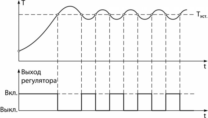
The ventilation mechanisms are controlled by a set of sensors installed inside the premises. Some of them operate on the principle of a thermostat - as the temperature inside the building rises, the fans automatically turn on, which ensures the flow of fresh air.
Modern automated systems are equipped with elements of artificial intelligence and more sophisticated instrumentation.
Structurally similar modules consist of three groups of nodes:
- Sensors - devices that transmit information about the environment - thermostats, air humidity meters, gas analyzers. They transmit the collected data to the analyzing center.
- The control center collects and processes the information coming from the control sensors, and, based on the obtained analysis, issues commands to the control mechanisms to change the operating mode.
- Actuators are units that carry out mechanical actions. This group includes: fan speed converter, servo drives for adjusting the position of the dampers, etc.
The control centers analyze the ratio of oxygen and carbon dioxide in the air, the percentage of humidity, and, if necessary, issue a command to ventilate the room. When a fire is detected, the highly intelligent electronics automatically blocks the flow of fresh air, preventing the spread of the fire.
In normal mode, the automation ensures the well-coordinated functioning of all units and mechanisms of ventilation systems without the involvement of an operator.
Computerized modules transmit information about the operating mode, about the readings of the sensors to a single control panel. This allows the operator, if necessary, to adjust the operation of the automation, and change the settings remotely.
Depending on the specific situation, one of 3 instrument control modes is used:
- Manual. The ventilation is controlled by an operator located directly in the control room, or behind a remote control panel.
- Autonomous. The equipment operates in accordance with the established settings, regardless of other engineering systems installed in the building.
- Auto. Control devices are integrated into the general management of all engineering complexes of the building. The ventilation operation is synchronized with other devices and sensors located in the house - for example, with a fire alarm, other emergency sensors.
Thus, the automated complex plays the role of a managing control center. It starts ventilation, stops it, processes the sensor readings and sets the desired mode depending on temperature, humidity and other parameters.
Ventilation control in case of fire
When designing ventilation automation systems, take into account their operation in the event of a fire.
According to SP 60.13330.2012, for buildings and premises equipped with automatic fire extinguishing installations or automatic fire alarms, automatic actions of electrical receivers of ventilation systems should be provided:
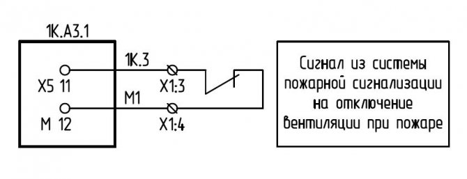
- Shutdown in the event of a fire in a room or in a ventilation system, which can be carried out centrally, cutting off the power supply and ensuring that the fire dampers on the distribution boards of the ventilation systems are closed, or individually for each system in order to prevent the spread of fire through the ducts and stop the flow of oxygen to the flame;
- Switching on smoke ventilation systems on escape routes and in security zones, or smoke ventilation in the room where the fire occurred, depending on the design solutions;
- Activation of systems for the removal of gas and smoke after a fire.
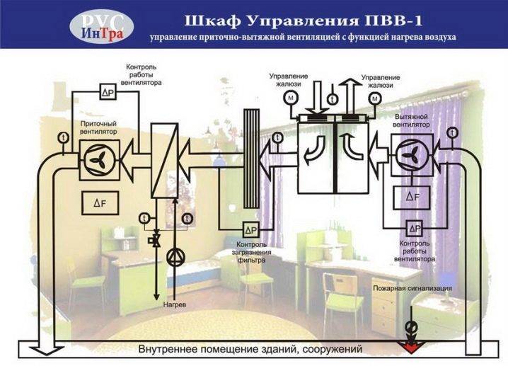
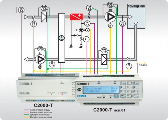
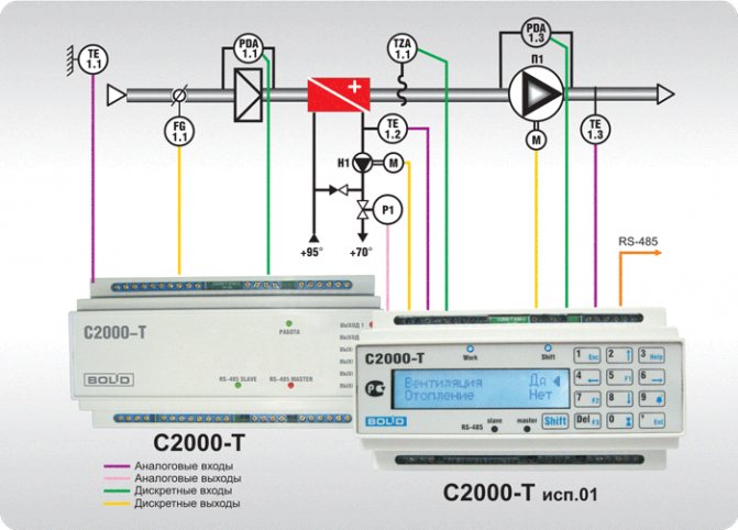
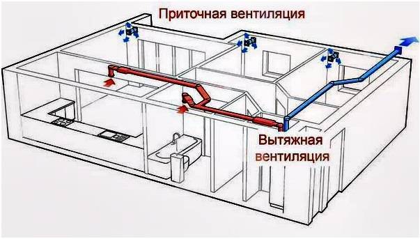
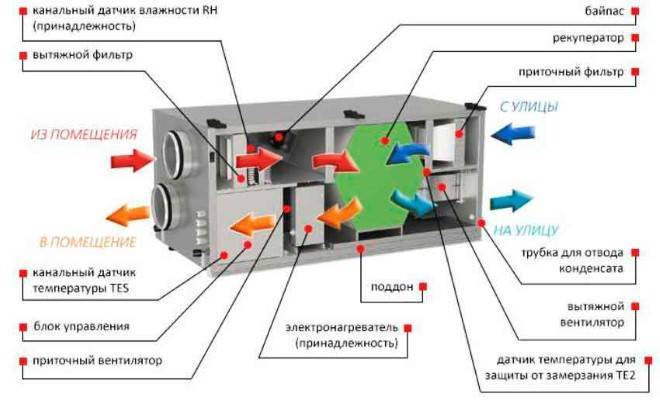
Types of supply and exhaust systems
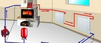
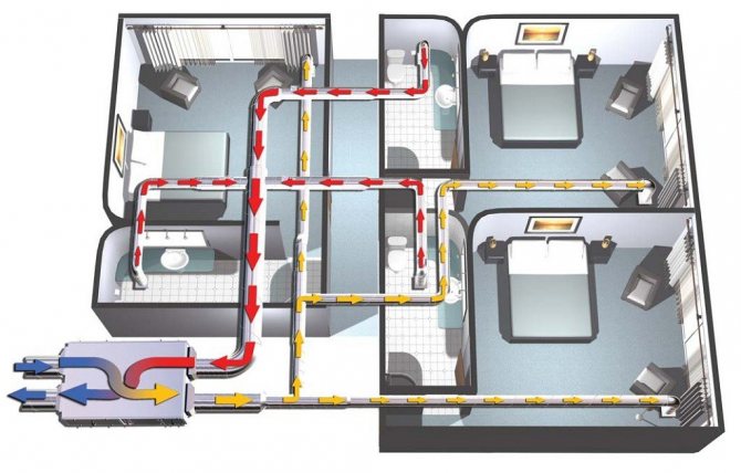
The most efficient ventilation systems are supply and exhaust, including recuperators in the circuit. These devices are heat exchangers that use the energy of the exhaust air. In this case, the inlet stream and the outlet do not come into direct contact. The recuperator can be rotary, plate or containing an intermediate heat carrier. The rotary one is highly efficient, but it is considered the most expensive. Its use is uneconomical when the outside air temperature during the cold period does not drop below 15 degrees below zero. At the same time, air handling units with rotary recuperators used in northern latitudes provide a twofold saving in energy costs for space heating. The plate version of the device is more affordable and belongs to the budget segment.
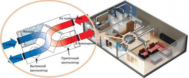
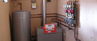
Installation with recuperator
In the cold season, the incoming air stream heats up in the room and, when it leaves, gives off heat to the newly incoming stream. The lack of mixing guarantees a constant supply of fresh, clean air and the removal of waste. In summer, in hot weather, the device works in the reverse order. The warm stream, entering the room, cools down, and when it leaves, it takes heat from the newcomer.
General exchange ventilation of circulation type is a cheaper type. The air entering from the outside receives heat by directly contacting the waste.
In this case, the cleanliness of the air in the room can no longer be the same as in the above-described version. Circulation systems cannot be installed in buildings where the atmosphere may contain carbon monoxide and combustible gases, toxic substances and other components dangerous to life and health.
Another disadvantage of forced circulation ventilation is its ineffectiveness when the outside temperature drops below zero.
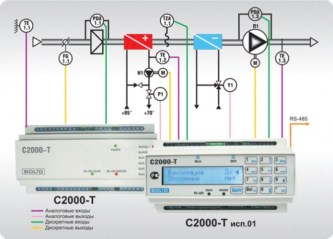
The most expensive options for air handling units with forced ventilation are systems equipped with air conditioners. The devices allow you to regulate the temperature regime in the room over a wide range and provide comfortable conditions all year round. The system is equipped with a heat pump and a filtration circuit for air purification.
Each of the forced ventilation is provided with a control system. The most expensive options are supplied with sensors and "smart" electronics, capable of regulating the modes independently, according to a predetermined program.
For ventilation of buildings, especially multi-storey buildings, not only mechanical air circulation can be used. The pressure difference inside and outside the room is able to create the flow necessary for ventilation. The supply and exhaust ventilation with natural circulation is based on this principle. In this case, the following nuances are taken into account:
- To place the air intake, the side of the building is usually chosen, which is most often blown by the wind.
- The retraction is made from the opposite side
- The air intake itself is equipped with a deflector that enhances the incoming flow.
Such a system is distinguished by its simplicity of design and low cost. However, simplicity excludes the possibility of saving heat and many advantages provided by installations with forced ventilation: ionization, cleaning, humidity control.
Connecting the fan to the electrical network
One of the stages in the installation of the ventilation system is to connect the fan to the electrical network. Below we will consider the features of connecting fans.
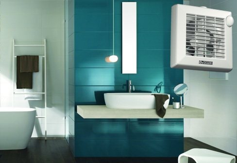
When connecting a ventilation fan, first of all, take into account the fact that the bathroom and toilet belong to rooms with a high level of humidity. Therefore, all elements of electrical wiring and fittings for its installation must have a housing with a sufficient level of protection against moisture. As a rule, the degree of protection of the case of the mounted structural elements of the electrical wiring is selected at least IP44.
How are the fans connected to the electrical network?
In this case, it all depends on its design features. There are types of fans that can be turned on and off by a built-in switch controlled by a cord. By pulling the strap down, the fan can be turned on or off.
Some fans provide the ability to open and close the ventilation hole, usually a switch is built into this closing and opening device. By pulling one rope, the hole opens and the fan starts to work, pulling the other rope, the fan opening closes and it is disconnected from the electrical network.
If the fan does not have the above devices or, for one reason or another, it is inconvenient to use them (for example, if the fan is high enough relative to the floor), then a switch must be installed to turn the fan on and off. For this purpose, switches used for lighting equipment are suitable, since the fan power is usually low.
As mentioned above, all electrical elements installed in the bathroom, including the switch, must be protected from moisture.
Where to get power for the fan?
The power consumption of this consumer of electrical energy is small, so if you have not laid a separate line to power it immediately, then you should not worry about this. It can be plugged into the nearest junction box, and if there is none, branch the line from one of the sockets located in the bathroom. If there is a socket in the bathroom, for example, for a washing machine, then you can connect a fan from it.
Bathroom fan connection diagram
Connecting a fan with a timer
The operating time of the fan in the bathroom or toilet can be set using a timer. For these purposes, both universal timers and fans with built-in timers can be used.
Fan connection diagram with built-in timer
Automatic fan activation
The bathroom ventilation fan can be switched on automatically. The main task of the fan, as mentioned above, is to reduce the level of humidity in the room, based on this principle, it is necessary to automatically turn on the fan in case of an increase in the level of humidity in the room. The humidity level sensor (hydrostat) switches on the ventilation fan if the humidity level in the room rises to the set value.
Hydrostat for fan control in the bathroom
Hydrostat connection diagram for fan control
For a toilet, where, in addition to reducing the humidity level, the fan eliminates unwanted odors, a humidity level sensor alone will not be enough. In this case, a motion sensor is installed to automatically turn on the fan. That is, when movement appears in the sensor detection area, it supplies voltage to the fan and, accordingly, if there is no movement in the sensor detection area, the fan turns off after a while. It is advisable to choose a motion sensor, in which it is possible to set the time after which the load is disconnected if there is no movement in the room.
In most cases, the installation of motion and humidity sensors in the room is neglected and limited to the installation of a switch for manually controlling the fan.
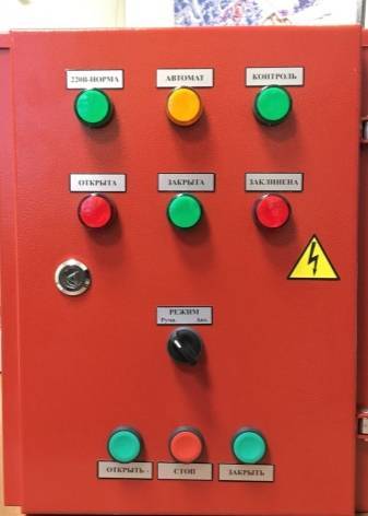
Functions of automatic ventilation cabinet
ventilation control cabinet "Rubezh-4A
Features of ventilation control cabinets:
- maintain the required constant power of the power grid;
- allow you to conveniently connect lines of different power voltages to different terminal blocks;
- control the intensity of rotation of the fans, start them smoothly and prevent phase imbalance;
- equalize power, preventing equipment overheating, overload and short circuits;
- control the voltage in the network autonomously, remotely or locally.
The supply and exhaust ventilation control cabinet operates in standby or summer modes. In summer mode, the air temperature is not controlled. When the supply air temperature is low, the cabinet automation switches the supply ventilation control to protection mode.
Standard functions
- Manual stop and start;
- compatible with temperature sensors for supply air, outdoor air, and return heat carrier;
- records the temperature of the fan motors contacts;
- regulates the function of the air valve actuator;
- prevents short circuits and overloads of the pump motor;
- controls the drive of the heat supply valve;
- prevents freezing of water heaters and freon coolers;
- prevents overheating of the electric heater;
- prolongs the stop of the supply air fan;
- gives signals about the need to clean the air filters;
- stops and de-energizes equipment in the event of a fire alarm;
- notifies with the help of light indication about the work of the system;
- records accidents in a special log.
Advanced functions
- Prevents pressure drops when the fan belt breaks;
- Provides frequency conversion for fans;
- Regulates indoor air temperatures in a cascade manner;
- compatible with a thermosensor on the hood;
- notifies about an accident with light indication;
- connection of remote control is possible;
- controls the operation of the air valve;
- provides connection of additional fans;
- two-phase control of the compressor-condenser unit;
- five-phase control by an electric heater;
- controls the mixing chamber;
- prevents freezing of the recuperator and rotary recuperator;
- controls air humidifiers;
- programmable for 7 days;
- controls the cooler valve;
- controls the recirculation dampers;
- in case of insufficient heating power, it reduces the rotation speed of the fan blades;
- saves data in memory after power outage;
- controls the level of carbon dioxide.
On request, manufacturers equip the cabinet for automatic ventilation control with additional features:
- work without sensors;
- recording of reports on the system operation;
- cold recovery;
- dispatching remote or local control.
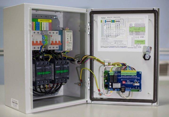
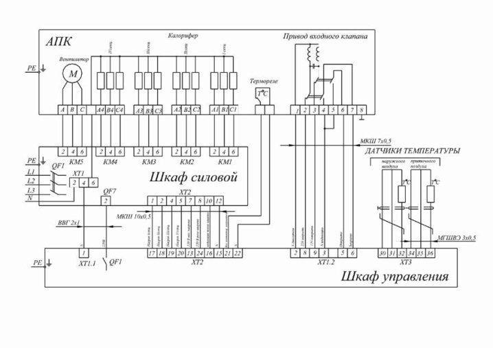
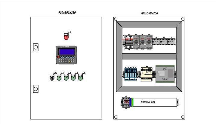
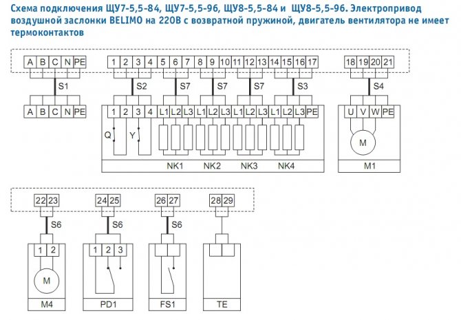
Ventilation control cabinet diagram
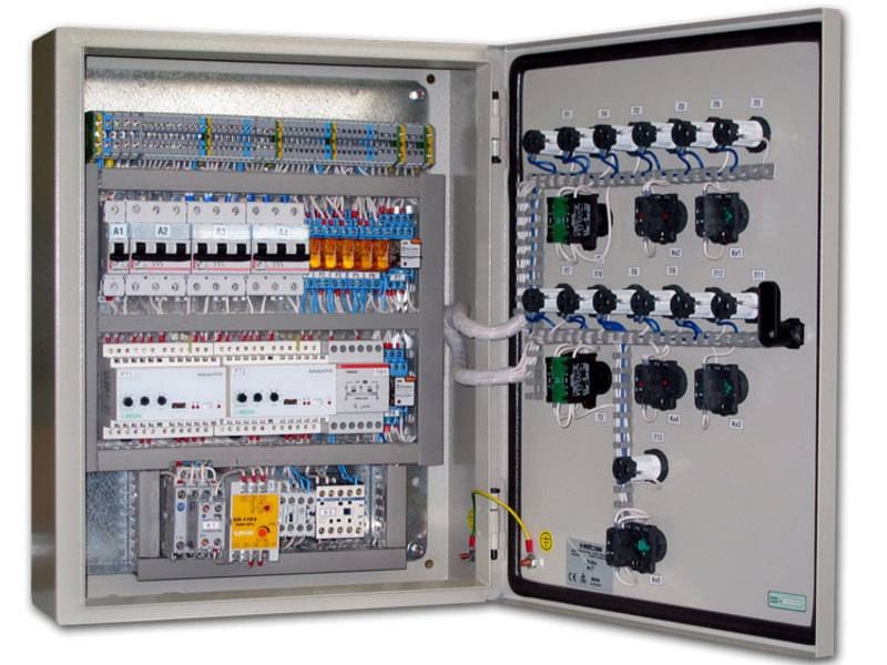
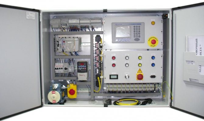
The ventilation control cabinet is arranged as follows:
- Private converter.
- Multiprocessor controller.
- Switch.
- Actuator.
- Automatic machines.
- Contactor.
- Defense mechanisms.
- Relay.
- Indicators.
Light and sound indicators provide control over the operation of the entire ventilation system of the room. The relay controls electrical circuits, opens and closes them. The contactor allows you to control the system using the remote control. The automata implement the flow of current into the electrical circuit. Starters for starting, a switch for disconnecting equipment in the cabinet. A multiprocessor pixel controller is often used to operate the memory card. The choice of the mode for a smooth start of the engine and a gradual increase in the rotation of the fan blades is carried out by a private converter.
We recommend that you read: Ventilation in the pool
Elements of ventilation systems
The control system includes basic elements such as sensors, regulators and other actuators.
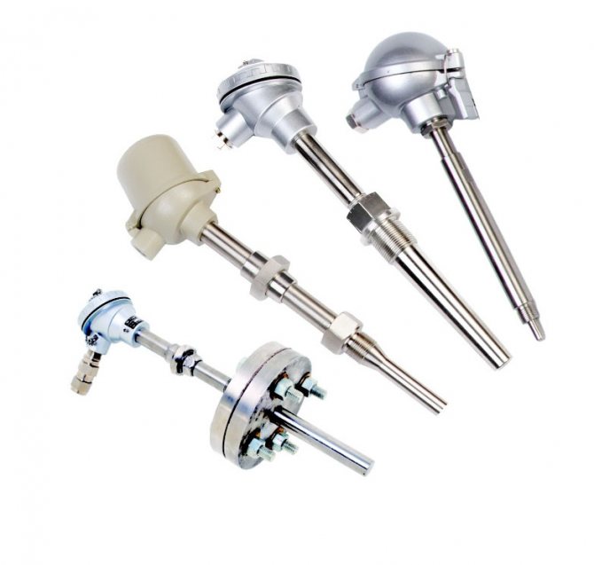
Sensors
With the help of sensors, you can receive information about the state of the required object by various parameters (temperature, pressure, humidity, etc.) and monitor it in the event of the slightest system failure. The sensors must be selected strictly in accordance with the conditions of a particular ventilation (operating conditions, range and degree of measurement accuracy, etc.).
Temperature sensors are made for outdoor and indoor use, they can show the temperature on the surface of the pipeline or inside the channel (air duct). They are fixed either on the pipes themselves (on their surface) - external, or perpendicular to the moving air flow in the pipe, duct - channel sensors. Atmospheric sensors are installed outside the building, above its middle, on the leeward side, and room types of sensors should be mounted indoors, at a distance of at least 1 - 1.5 m from the floor.
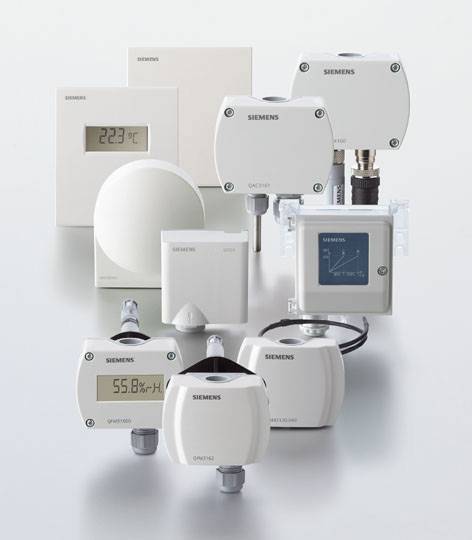
Ventilation and heating system sensors
Ventilation control also depends on sensors that regulate the degree of humidity, they are for indoor and duct purposes. Outwardly, they look like a unit with a built-in electrical device that measures the relative humidity of the air and converts the received data into electronic signals. In order for the device to work more accurately, it must be installed at a certain distance from windows, heating devices, ventilation jets and sunlight.
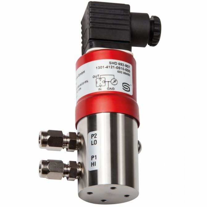
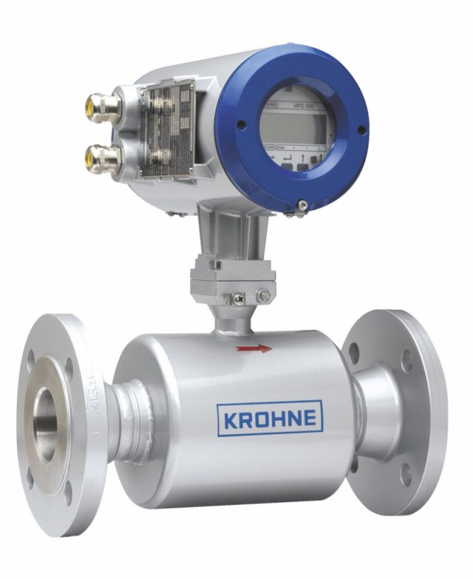
Flow sensors are devices that measure the speed of flow (it can be both liquid and gas) in pipes and air ducts. The calculation of the gas or liquid flow rate is made taking into account the cross-sectional area of the pipe.
Regulators
Regulators are required to control the executive ventilation mechanisms. They receive signals from sensors, process their readings and activate the actuators of the ventilation system.
Regulators for control of executive ventilation mechanisms
Actuators
A device that starts its work on a command received from the regulator is called an actuator. They are divided according to the way of work: electrical, mechanical, hydraulic, etc.
All processes that make up the entire ventilation control system are controlled by a device such as an electrical control panel.
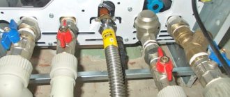
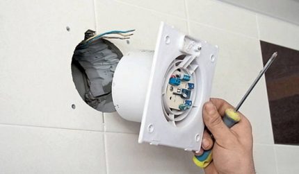
Installation features
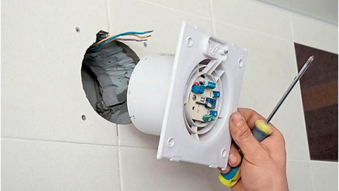
The fan is connected to a two-wire cable. First, the front panel is removed from the device. A strobe is laid from the distribution box to the ventilation hole. It should be strictly vertical or horizontal, without oblique lines.
The fan terminals are marked in English:
- L - phase.
- N - zero core.
- T - to connect the signal wire. Used in models with a timer.
The veins vary in color. Zero is blue, the phase is in brown or white isolation. They must be correctly connected to the fan terminals and check the reliability of the contact. There are 4 holes for screws or self-tapping screws on the body of the device. Fasteners are included in the scope of delivery. The fan can also be mounted on tiles without drilling. Silicone glue is suitable for this. You can use liquid nails.
On the wall
The device is applied to the surface. With a pencil or marker, mark the drilling sites. An impact drill or hammer drill is suitable for forming the mounting holes. It is necessary to use drills with victorious soldering. After drilling holes of the required depth, plastic dowels are hammered into them.
The hood is inserted into the vent and secured with complete screws. Then you can start connecting the device. The scheme depends on the characteristics and functionality of the model.
We suggest you familiarize yourself with a bathroom with a window - 53 photos of ideas on how to beat a window in a bathroom
Algorithm for wall mounting without drilling:
- The surface of the wall at the attachment point is cleaned.
- Silicone glue or liquid nails are applied along the contour
- The device is applied to the opening of the ventilation duct.
- A level is used to check the horizontal.
- The fan is fixed with tape for 2-3 hours.
The final stage is power supply and return to the place of the decorative panel.
On the ceiling
With a stretch or suspended ceiling system, the task is somewhat more complicated. Often the place for the installation of an exhaust fan in the bathroom is laid at the design stage of the house. The ventilation grill or cooler is attached to the plasterboard panel with butterfly dowels.
The device is fixed on the polyvinyl chloride film using a predetermined rigid base. With the suspended ceiling installed, the communications are pulled through a pre-prepared hole or run along the base surface and hidden with a cable channel.
Several modifications of the exhaust fans are available. They are lace-up, with timers, motion sensors, mode switches, etc.
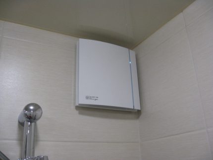
The most popular exhaust fan options are equipped with built-in humidity sensors. They extract stuffy air from the room, control moisture levels and consume a small amount of electricity.
Models with a humidity sensor are most effective - they turn on automatically when the humidity level in the room rises. Manufacturers of exhaust systems have released such “smart” variations of fans in order to increase the level of user comfort - after all, after taking a shower, you can forget to manually turn on or off the fan.
Now let's talk about how the humidity sensor installed in the exhaust fan works. The internal structure and principle of operation of such devices practically does not differ from standard exhaust devices. When the engine is turned on, the blades begin to spin.This sets the air in motion and draws it along with the moisture droplets into the exhaust shaft.
The hood with a sensor can be mounted on a ceiling or wall ventilation shaft. The body and parts of the product are made of waterproof materials. The electrical parts are of high quality insulation.
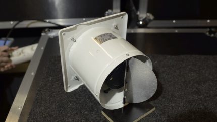
The most expensive models of exhaust systems with a humidity sensor are additionally equipped with a backlight, as well as a special check valve that does not let unpleasant odors and dust into the room from the duct
The humidity sensor in the fan can be operated both by timer and automatically. In the second case, the exhaust system turns on when the humidity level in the room exceeds the norm.
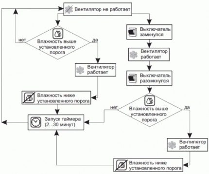
The scheme of the fan operation with a sensor that controls the humidity level. When the moisture level rises, the product turns on and works until the readings return to normal. Shutdown occurs by delay timer
In general, a humidity sensor or hygrostat in a fan is a special element that allows you to measure the level of humidity in the air and start the exhaust device without human intervention. And all this thanks to the high sensitivity of the sensor to condensation. It works on the principle of a thermostat, ventilation is turned on only at humidity above 40%.
Exhaust systems with integrated hygrostat are ideal for installation in bathrooms, drying rooms and toilets. Can be used as basement ventilation in private houses.
Humidity sensors are usually equipped with models of axial duct fans. A small-sized board is mounted in the product body. There are two limits in a hygrostat: an upper and a lower one.
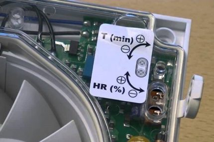
In order for the fan to work for a long time and correctly, it must be properly configured. In the structure of the sensor there is a regulator, which is equipped with a humidity scale. The moisture level is set by turning the potentiometer
Some variations are preset from the factory and cannot be adjusted. On the rest, the response range can be set independently.
Types of sensors:
- Resistive - when the humidity level changes, the product changes resistance and starts the fan motor.
- Dielectric - has a capacitor in the design. With an increase in humidity between the plates of the product, the dielectric constant of the medium changes.
- Thermistor - an improved analog of a resistive sensor. Has increased accuracy.
- Optical - determines the concentration of humidity based on the transparency of the air.
- Mechanical - when there is more moisture in the room, the length of the material from which the sensor is made changes.
When the humidity level reaches the programmed values in the sensor, the relay is activated. It closes the motor's electrical circuit and the fan starts spinning.
An exhaust system with a humidity sensor is mounted similarly to a simple fan. Only the connection diagram of the device can differ. Be sure to look at the fan installation instructions. Usually, manufacturers provide the correct connection diagram in the passport.
We suggest that you familiarize yourself with Plasterboard tiles in the bathroom with your own hands, instructions from the masters
The hood should be installed when the mains voltage is removed. Before installation, you need to prepare the exhaust shaft and check it for patency and blockages.
Before connecting the exhaust system, the ventilation shaft must be cleaned of debris, dust and the cobwebs must be removed. Next, check the patency of the air duct using a burning match, lighter or sheet of paper.
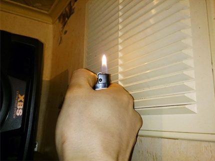
To check for the presence of airflow, an open flame is brought to the ventilation hole. If the flame has deflected towards the duct, then there is a draft
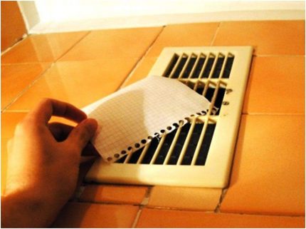
You can check natural ventilation without special devices. To do this, a sheet of paper is applied to the opening of the hood (strangler) and released.If the leaf does not fall, then everything is fine with the air flow.
If there is little or no air flow, you need to find the blockage and clean the exhaust system. If you cannot find the blockage yourself, you can contact special services, they will clean the mine.
Before installing the fan, you need to make sure that fresh air also enters the bathroom or toilet. He can get into the room through windows or cracks under the doors. If the room is completely sealed (blind windows, there is no gap between the door leaf), you need to install special grilles in the door.
Several connection schemes can be used to connect a fan in a bathroom or toilet. They differ among themselves in the option of supplying power to the exhaust device.
It is better to lay the wiring under the hood during repairs in order to hide it in the wall. If this is not possible, the cable can be masked by means of a decorative box or special overlays.
The exhaust system is connected to the mains using a separate switch, to a light switch or via a sensor.
Fan connection diagram through a light bulb. The device is connected in parallel with the lighting. When the light turns on, the duct fan starts to work. When the light is off, the product does not function
Connection diagram for an exhaust fan with a separate switch. In this variant, you need to turn on and off the exhaust device yourself.
These connection methods are not suitable for exhaust units with a hygrostat.
There is a special circuit for switching on a duct fan using a humidity sensor.
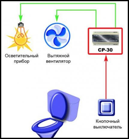
Connection diagram through automation. It is suitable for fans equipped with a humidity sensor, as well as for devices that operate on a timer.
It is not difficult to connect a fan with a sensor or timer if you read the instructions and do everything according to the scheme. The product is connected to a 220 V network through the terminal box located under the fan cover.
Connecting wires to terminals:
- LT - cable with a phase coming from an external switch;
- N - zero;
- L - wire with phase.
Connect the product through three wires - all terminals are signed. The exhaust system can be tied from a lighting lamp. The fan will start working when voltage is applied to the terminal marked LT (light on). Shutdown is performed 2-30 minutes after the lamp is turned off.
A fan with a humidity sensor can turn on automatically when the humidity in the room exceeds the set level on the hygrometer. When the moisture becomes less, the product will work for some more time according to the delay timer and turn off on its own.
Before installing the fan in the shaft, you need to make sure that all the wires are connected. The decorative grille must be removed from the duct. You can connect the device to the mains through the terminal box.
Each wire has its own color marking: the phase can be red, white or black, and zero is blue