Features of the installation of gas boilers and furnace equipment
The installation of gas boilers must be carried out in accordance with the requirements of regulatory documents. The tenants themselves, the owners of the building cannot install gas equipment. It should be installed in accordance with a project that can only be developed by an organization licensed to do so.
Gas boilers are also installed (connected) by specialists from a licensed organization. Trading companies, as a rule, have permits for after-sales service of automated gas equipment, often for design and installation. Therefore, it is convenient to use the services of one organization.
Below, for informational purposes, the basic requirements for the places where boilers operating on natural gas can be installed (connected to the gas main) are given. But the construction of such structures must be carried out in accordance with the project and the requirements of the standards.
Different requirements for boilers with a closed and open combustion chamber
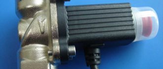
All boilers are classified according to the type of combustion chamber and the way it is ventilated. The closed combustion chamber is ventilated forcibly using a fan built into the boiler.
This allows you to do without a high chimney, but only with a horizontal section of the pipe and take air for the burner from the street through an air duct or the same chimney (coaxial chimney).
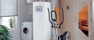
Therefore, the requirements for the installation site of one low-power (up to 30 kW) wall-mounted boiler with a closed combustion chamber are not so stringent. It can be installed in a dry utility room, including the kitchen.
Installation of gas equipment in living rooms is prohibited, in the bathroom is prohibited
Boilers with an open burner are another matter. They work for a high chimney (above the ridge of the roof), which creates a natural draft through the combustion chamber. And the air is taken directly from the room.
The presence of such a combustion chamber entails the main limitation - these boilers must be installed in separate rooms specially allocated for them - furnace (boiler rooms).
Learn more about the features of boilers with different combustion chambers. And also learn about choosing an economical boiler and creating an economical heating system.
Next, we will consider in more detail the requirements for the placement of boilers within the furnace, and for this room.
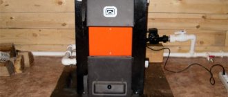
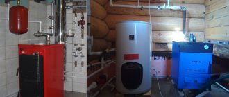
Where can the furnace (boiler room) be located
The room for installing boilers can be located on any floor of a private house, including in the basement and basement, as well as in the attic and on the roof.
Those. under the furnace, you can adapt a room within the house with dimensions not less than the standard, the doors from which lead to the street. And also equipped with a window and a ventilation grill of a certain area, etc. The furnace can be located in a separate building.
What and how can be placed in the furnace
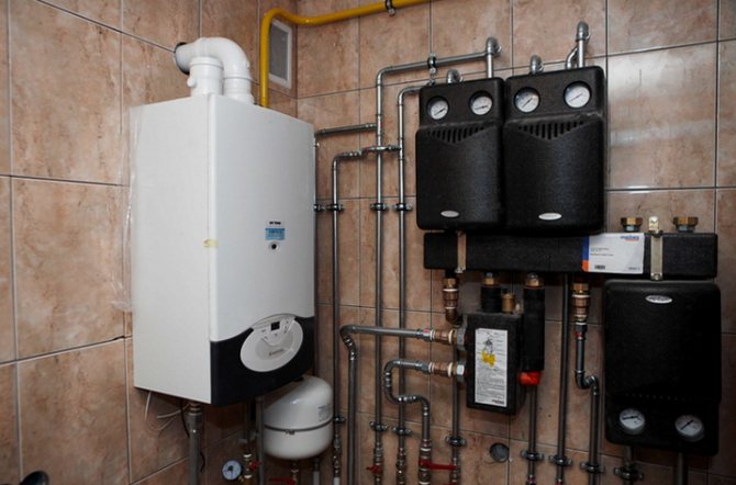
The free passage from the front side of the installed gas equipment must be at least 1 meter wide. The furnace can accommodate up to 4 units of gas heating equipment with closed combustion chambers, but with a total capacity of no more than 200 kW.
Furnace dimensions
The height of the ceilings in the furnace (boiler room) is at least 2.2 meters, the floor area is at least 4 square meters. for one boiler. But the volume of the furnace is regulated depending on the capacity of the installed gas equipment: - up to 30 kW inclusive - not less than 7.5 cubic meters; - 30 - 60 kW inclusively - not less than 13.5 cubic meters; - 60 - 200 kW - at least 15 cubic meters
What is equipped with a furnace
The furnace is equipped with doors to the street with a width of at least 0.8 meters, as well as a window for natural lighting with an area of at least 0.3 square meters. 10 cubic meters. furnace.
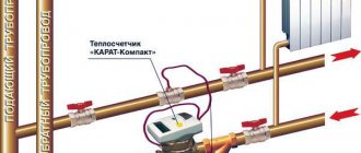
The furnace is supplied with a single-phase 220 V power supply, made in accordance with the PUE, as well as a water supply system connected to heating and hot water supply, as well as a sewage system that can receive water in case of emergency flooding, including in the volumes of a boiler and a buffer tank.
The presence in the boiler room of combustible, fire hazardous materials, including finishing on the walls, is not allowed. The gas main within the furnace must be equipped with a shut-off device, one for each boiler.
How the furnace (boiler room) should be ventilated
The furnace must be equipped with exhaust ventilation, possibly connected to the ventilation system of the entire building. Fresh air can be supplied to the boilers through the ventilation grill, which is installed at the bottom of the door or wall.
Moreover, the area of the holes in this grate should not be less than 8 cm square per one kilowatt of boiler power. And if the inflow from inside the building is at least 30 cm square. for 1 kW.
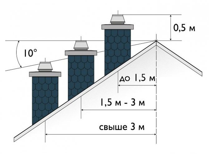
Chimney
The values of the minimum diameter of the chimney depending on the boiler output are given in the table.
But the basic rule is this - the cross-sectional area of the chimney should not be less than the area of the outlet in the boiler.
Each chimney must have an inspection hole located at least 25 cm below the chimney inlet.
For stable operation, the chimney must be above the roof ridge. Also, the chimney trunk (vertical part) must be absolutely straight.
This information is provided for informational purposes only to form a general idea of the furnace in private houses. When building a room for placing gas equipment, it is necessary to be guided by design solutions and the requirements of regulatory documents.
Great Encyclopedia of Oil and Gas
Page 4
For all boilers of this group, the combustion chamber is divided by a two-light screen. A further reduction in the dimensions of the boilers was achieved due to the fact that, with the smaller dimensions of the convective part of the superheater, it became possible to reduce the depth of the horizontal bypass flue, and reduce the distance between the furnace and the lowering convection shaft. In particular, for the TP-92 boiler, the entire primary superheater is made in the form of wall-mounted tube packages and screens arranged in two rows, and the secondary superheater is located in a downward convection shaft. [46]
Because of this, there should be no downward fluid paths in the piping at the top of the economizer. This determines the design of parallel tubes in the coils, which are somewhat larger than the coils of the convective part of the superheater. [47]
In the superheater, there is no mutual crossing of steam from the left and right halves of the boiler and the steam temperature is regulated for each half separately. Further, the steam along the vertical risers 7, inside which there is an injection device, is directed to the lower half of the convective part of the superheater. [49]
If an incendiary belt hung on these pipes, then cracks would periodically appear in it. Therefore, if there is an incendiary belt in the firebox, it is necessary to abandon the installation of a high radiation steam superheater. Accordingly, the convective part of the superheater increases and a part of its heating surface must operate at a reduced temperature head. This circumstance creates additional difficulties. [fifty]
If the feed water enters the drum boiler at a lower temperature, then additional fuel must be consumed to heat this water to a boil. In this case, the screens and the convective part of the superheater are heated by an increased amount of flue gases, and the superheat of the steam increases accordingly.In a once-through boiler such an increase in fuel consumption leads to an increase in the temperature of the reheat steam. [52]
| Boiler superheater diagram TGM-84B. [53] |
The boiler was repeatedly reconstructed, as a result of which the TGM-84A model appeared, and then the TGM-84B model. In particular, unified screens were introduced and a more even distribution of steam between the pipes was achieved. The transverse spacing of pipes in the horizontal packages of the convective part of the superheater was increased, thereby reducing the likelihood of its contamination with fuel oil soot. [54]
The coils of the heating control surface located above it have become unusable. On a much smaller scale, the last vertical coils of the convective part of the superheater were damaged in the course of gases; the economizer and the regenerative rotary air heater were not damaged. [55]
The gas-tight combustion chamber with all-welded screens and solid bottom ash removal is equipped with eight double-flow pulverized coal burners located oppositely on the side walls in one tier. The layout of the boiler is made according to the T-shaped scheme with downward gas ducts located on the sides of the furnace, in which the convective part of the superheater and the second stage of the economizer are located. [57]
In a drum boiler, the temperature of the superheated steam, as a rule, rises with an increase in the moisture content of the coal and decreases with a decrease. This dependence is most felt in boilers, in which the radiation part of the superheater is relatively small, and is mainly explained by the fact that when burning more humid coal, the amount of flue gases that wash the screens and the convective part of the superheater increases, as a result of which a greater amount of heat is transferred to the steam. [58]
Much more dangerous is a temporary increase in the salinity of feed water due to various operational problems, for example, etc. This zone is located as. Ramzin, between the convective part of the superheater and the convective economizer and is washed, therefore, by flue gases of moderate temperature. The feasibility of such a transition zone will be tested in the first years of operation of the boilers. [59]
The superheaters of several boilers operating at ASh are arranged differently (Fig. Saturated steam enters the radiant part of the superheater, located on one side wall of the furnace. This part of the superheater consists of two panels. Then the steam enters the convective part of the superheater, consisting of three packs of horizontal coils and located in a lifting gas duct above a small boiler tube bundle. [60]
Pages: 1 2 3 4 5
www.ngpedia.ru
Determination of the dimensions of the combustion chamber, convection flue and placement of burners
The combustion chamber of the designed boiler is a parallelepiped (at - width, bt - depth, ht - height)
The volume of the combustion chamber is limited by the axial plane of the wall and ceiling wall tubes. The section of the furnace along the axes of the pipes of the screens fт is determined on the basis of the density of heat release tested in practice along the section of the furnace qf
fт =, m2 (9)
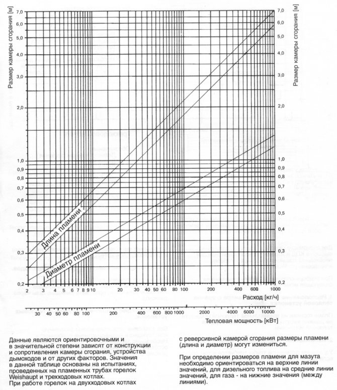
The width and depth of the combustion chamber are selected based on the dimensions of the burners flame and their heat output. The course project uses Weishaupt [] automatic burners. The dimensions of the section of the combustion chamber are determined according to the nomogram in Fig. 9.1.
Figure 9.1
Heat output of the burner
, kW (9.1)
where Вр is the volumetric consumption of natural gas, m3 / h;
- the lowest heat of combustion of gas, kJ / m3.
In boilers with low productivity (up to 25 t / h), one burner is installed per boiler. The type of suitable burner is selected from the catalog [].
The result of the choice of the burner is presented in table. 9.1
Table 9.1
| Burner type | number |
| Monarh gas-oil 1000 ... 1000 kW |
The volume of the boiler combustion chamber is selected based on the permissible thermal stress of the combustion volume.
, m3 (9.2)
The results of calculating the section, volume and height of the combustion chamber are presented in table. 9.2
Table 9.2
| , m3 / s | , kJ / m3 | , kW / m2 | , m2 | , kW / m2 | , m3 | ht, m |
The smallest section of the convective gas duct is determined based on the volume of gases at the entrance to the mine and on their economically optimal speed
, m2 (9.3)
where Fk is the section, m2; - temperature of flue gases at the entrance to the gas duct, оС; K is the coefficient of the free flow area; - optimal speed of flue gases, m / s.
Free flow area ratio
, (9.4)
where S1 is the pipe pitch in the cross-section transverse to the gas flow, mm; d - outer diameter of pipes, mm.
S1 S1 d
gas flow
Pre-selected d = 51 mm, S1 = 100 mm. The calculation results are presented in table. 9.3
Table 9.3
| , m3 / h | , m3 / s | Vg, m3 / m3 | , oC | , m / s | S, mm | d, mm | TO | , m2 |
The calculated surface of the walls of the combustion chamber
, m2 (9.5)
Estimated volume of the combustion chamber
, m3 (9.6)
The result of the determination is presented in table. 9.4
Table 9.4
| , m | , m | , m | , m2 | , m2 |
Thermal calculation of the combustion chamber
10.1. Useful heat dissipation in the firebox
, kJ / m3 (10)
where is the net calorific value of dry natural gas, kJ / m3; - the heat of the outside air. Since cold air is not preheated
, kJ / m3 (10.1)
The calculation results are given in table. 10.1
Table 10.1
| , kJ / m3 | , % | , kJ / m3 | , kJ / m3 | , kJ / m3 |
Theoretical (adiabatic) fuel combustion temperature.
Temperature, υa is determined from the table. 7.3 by interpolating the enthalpy of the combustion chamber gases using the formula
, оС (10.2)
The calculation result is presented in table. 10.2
Table 10.2
| , kJ / m3 | , оС | , оС | , kJ / m3 | , kJ / m3 | , оС |
megaobuchalka.ru
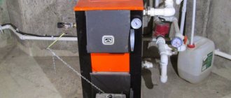
Owner reviews of Tis solid fuel boilers: advantages and disadvantages
| Benefits | disadvantages |
| Thick steel (4-5 mm) of the combustion chamber, which ensures the durability of the main element of TT boiler units | Large weight of boilers |
| Efficiency of fuel combustion due to the afterburning of gases and a more complex design of the removal of combustion products in younger models, as well as upper combustion in older models | Service and trade structures are not developed in all regions of Russia |
| Burning time - due to the relatively large firebox, depending on the model and fuel, one load is enough for 6.8, 10 or even 20 or more hours | According to service practice, there are extremely rare problems with a mechanical thermostat, the boiler does not maintain the set temperature |
| Moderate soot formation, no condensation problems, practical and easy to clean | |
| Pleasant cost for this class and price segment of boilers | |
| Excellent and responsive support (both in consultation before purchase and in further service) | |
| Large selection of power options for all models |
3.6. Steam boilers of the KE series
The brand of steam boilers of the KE series indicates double-drum units with natural circulation, layered furnaces with a steam capacity of 2.5 ... 25 t / h, which are designed to generate saturated and superheated steam with a pressure of 1.4 and 2.4 MPa. These steam boilers operate on black and brown coals, the set of boilers includes semi-mechanical furnaces KE-2.5-13 or mechanical furnaces TLMZ and TCHZ (steam boilers KE-4-13; -6.5-13; -10-13) ...
Steam boilers of the KE series, steam capacity 4; 6.5 and 10 t / h have a low layout with a combustion chamber (Fig. 3.8), formed by side screens of pipes with a diameter of 51 × 2.5 mm, front and rear unscreened brick walls.
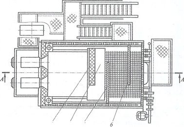
Fig. 3.8. Steam boiler of the KE series with a steam capacity of 4; 6.5 and 10 t / h:
1 - combustion chamber; 2 - upper drum; 3 - brick wall; 4 - afterburner chamber; 5, 6 - respectively, refractory and cast iron partitions; 7 - blowing device; 8 - lower drum; 9 - section for air supply; 10 - return grate; 11 - slag mine; 12 - pneumomechanical fuel spreader
An afterburner is located between the combustion chamber and the convective tube bundle. Flue gases from the combustion chamber and the afterburning chamber enter the convective tube bundle, washing it with a transverse flow and making turns in the horizontal plane during movement due to the presence of chamotte and cast-iron partitions. The side walls are covered with on-pipe lining.It is inclined under the afterburner so that the bulk of the fuel pieces falling into the chamber rolls onto the grate.
Steam boilers KE-25 are made in a high configuration with a fully screened firebox. The rear screen forms a scallop and, accordingly, an afterburner chamber. The right side L-shaped screen goes into the ceiling. The boilers are equipped with a fuel entrainment return system and a sharp blast (high-speed air flow). The entrainment settling in the four ash pans of the boiler is returned to the furnace by means of ejectors and is introduced into the combustion chamber. Blast air is introduced into the combustion chamber through the rear wall using nozzles located at a height of 500 mm from the grate level. A mechanical furnace is located under the boiler, which consists of a flake chain lattice of the return stroke. The grate is equipped with two pneumatic mechanical spreaders
The boiler uses a single-stage evaporation scheme. Feed water is fed into the upper drum under the water level through a perforated pipe. Steam is purified from moisture in a horizontal louvred separator and a steam receiver in the form of a perforated shield with holes.
The tail heating surfaces consist of a single-pass air heater, which provides air heating up to 145 ° C. A water economizer is installed behind the air heater.
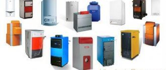
Which boiler model is better to choose in the end?
If you have opted for Tis boilers, the most versatile and widespread is the Tis Pro DR. In our opinion, this is the best offer in terms of price-quality ratio. In general, there are no unsuccessful or overly prominent models in the lineup. The choice depends primarily on the budget, as well as the type of fuel and its fragmentation.
The main thing in the choice is to decide on the required boiler power. For an average house in the climatic zone of the Moscow region, with 2 bricks and a ceiling height of 2.7 m, the minimum required heating equipment power is calculated from a simple rule: 1 kW for every 10 m2 of area. We also recommend setting a small margin of 15-25%.
For example, having the above-described house with an area of 150 m2, the minimum required power is 150/10 * 1.2 (20% of the stock) = 18 kW.
If the house is perfectly insulated (for example, foam plastic with a thickness of 10 cm or more) or is located in the extreme southern point of a country with a warm climate, the result can be adjusted downward by 5-30%.
How to calculate the required boiler power Individual calculation, formula and correction factors
Official site: where to see all models and operating instructions
A snapshot of the manufacturer's official website.
The original official website is at: https://www.belkomin.com/
In Russia, the enterprise is not represented by a single website, almost each of the official partners on the territory of the Russian Federation (you can see their list in the "Where to buy" section of the official website) has its own website.
Going to the section "Catalog" → "Solid fuel boilers" you can see all the available models and their descriptions. For each model, in the "Instruction" tab, electronic copies of a full-fledged instruction manual, installation and adjustment are attached. The manuals of each model describe the characteristics, the installation diagram, the algorithm for switching on and adjusting the operation, the features of service, there are clear schematic images and photos.
Service phone numbers differ depending on the region, you can find them by going to the tab "Service" → "Service centers".