Even the newest and most innovative heating equipment installed in the house may turn out to be useless, since it is not able to work harmoniously in a single heating complex. The connecting link of numerous units and elements of the thermal system is the coolant and its optimal hydraulic regime. If the owner of a residential building decides to create an economical and efficient heat supply system, he will need to know how to perform a hydraulic calculation of the heating system.
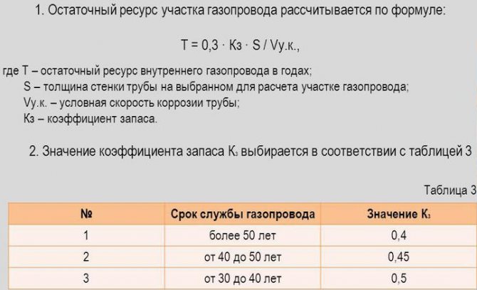
What else is taken into account when calculating the gas pipeline
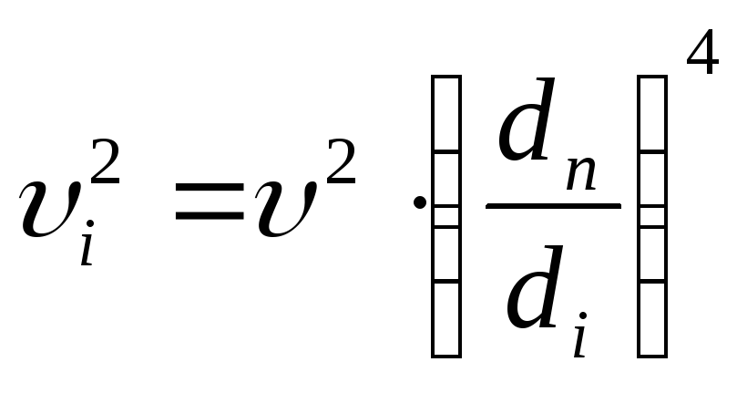
As a result of friction against the walls, the gas velocity over the pipe section differs - it is faster in the center. However, the average indicator is used for calculations - one conditional speed.
There are two types of movement through pipes: laminar (jet, typical for pipes with a small diameter) and turbulent (it has a disordered nature of movement with involuntary formation of vortices anywhere in a wide pipe).
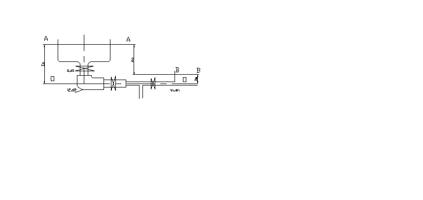
Calculation of the diameter of the main gas supply pipeline
Gas moves not only because of the external pressure exerted on it. Its layers exert pressure among themselves. Therefore, the hydrostatic head factor is also taken into account.
The movement speed is also influenced by the pipe materials. So in steel pipes during operation, the roughness of the inner walls increases and the axes narrow due to overgrowth. Polyethylene pipes, on the other hand, increase in inner diameter with decreasing wall thickness. All this is taken into account at the design pressure.
System selection
Selecting the type of pipeline
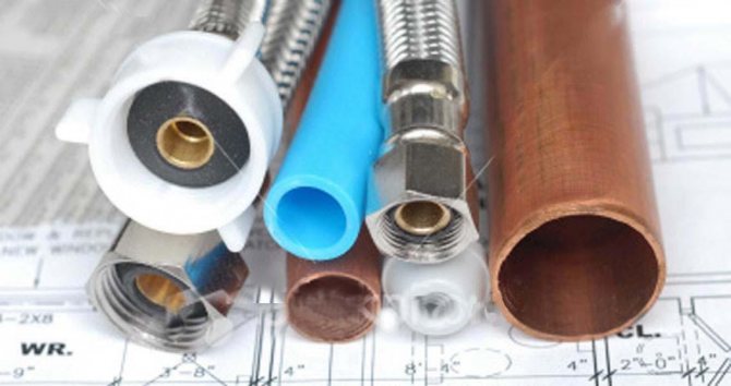
It is necessary to determine the material of the heating pipes:
Steel pipes are practically not used today, because due to their susceptibility to corrosion, their service life is short, installation is laborious, and repairs are difficult. Experts do not recommend using metal-plastic pipes because of their properties under the influence of temperature, sometimes they burst at bends. Copper pipes are the most durable and easy to repair, but also the most expensive. Various types of plastic pipes (for example, made of XLPE or reinforced polypropylene) are often the best choice
If a private house will be heated with plastic pipes, when choosing their brand, it is necessary, first of all, to pay attention to the indicator characterizing the permissible water pressure in the product .. To prevent deformations and bends of plastic pipes, you need to avoid very long straight sections
It is also necessary to observe during the first start-up of the heating system for a sharp change in temperature.
To prevent deformations and bends of plastic pipes, very long straight sections should be avoided. It is also necessary to observe during the first start-up of the heating system for a sharp change in temperature.
The main parameters of pipes
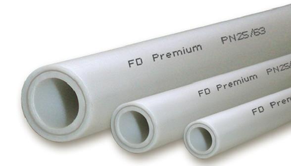
Polypropylene heating pipes of different diameters
For a heating system, pipes are selected not only for the chemical and physical properties of their material. In the design of an effective and economical system, their diameter and length play an important role, since the cross-section of the pipes affects the overall hydrodynamics. A fairly common mistake is the choice of products of too large a diameter, which leads to a decrease in the pressure in the system below normal, and the heating devices stop heating. If the diameter of the pipes is too small, the heating system begins to make noise.
Main characteristics of pipes:
- The inner diameter is the main parameter of any pipe.It determines its bandwidth.
- The outer diameter must also be considered when designing the system.
- Nominal diameter is a rounded value expressed in inches.
When choosing pipes for heating a country house, you need to take into account that different measurement systems are used for products made of different materials. Almost all cast iron and steel pipes are marked according to the inner section. Copper and Plastic Products - Outside Diameter
This is especially important if the system is to be installed using a combination of materials.

Example of matching pipe diameters from different materials
When combining different materials in the system, in order to select the pipe diameter accurately, you need to use the diameter correspondence table. It can be found on the internet. Diameter is often measured in fractions or inches. One inch equals 25.4 mm.
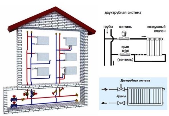
Two-pipe home heating system features of calculation, diagrams and installation
Even in spite of the relatively simple installation process and the relatively small length of the pipeline in the case of one-pipe heating systems, in the market of specialized equipment, two-pipe heating systems still remain in the first positions.
Although a short, but very convincing and informative list of the advantages and benefits of a two-pipe heating system, it justifies the purchase and subsequent use of circuits with a direct and return line.
Therefore, many consumers prefer it to other varieties, turning a blind eye to the fact that the installation of the system is not so easy.
How to work in EXCEL
The use of Excel tables is very convenient, since the results of hydraulic calculations are always reduced to tabular form. It is enough to define the sequence of actions and prepare exact formulas.
Input of initial data
A cell is selected and a value is entered. All other information is simply taken into account.
- the D15 value is recalculated in liters, so it is easier to perceive the flow rate;
- cell D16 - add formatting according to the condition: "If v does not fall within the range 0.25 ... 1.5 m / s, then the background of the cell is red / the font is white."
For pipelines with a difference in inlet and outlet heights, static pressure is added to the results: 1 kg / cm2 per 10 m.
Presentation of results
The author's color scheme carries a functional load:
- Light turquoise cells contain raw data - you can change it.
- Pale green cells - constants to be entered or data that are little subject to change.
- Yellow cells - auxiliary preliminary calculations.
- Light yellow cells - calculation results.
- Fonts: blue - initial data;
- black - intermediate / non-main results;
- red - the main and final results of the hydraulic calculation.
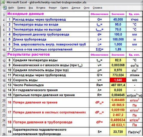
Results in Excel table
Example from Alexander Vorobyov
An example of a simple hydraulic calculation in Excel for a horizontal pipeline section.
- pipe length 100 meters;
- ø108 mm;
- wall thickness 4 mm.

Local resistance calculation results table
By complicating step-by-step calculations in Excel, you better master the theory and partially save on design work. Thanks to a competent approach, your heating system will become optimal in terms of costs and heat transfer.
Calculation of the pipe diameter

The calculation of the pipe cross-section should be based on the results of the thermal calculation, which are economically justified:
- for a two-pipe system - the difference between tr (hot heat carrier) and to (cooled - return flow);
- for one-pipe - the flow rate of the heat carrier G, kg / h.
In addition, the calculation should take into account the speed of movement of the working fluid (heat carrier) - V. Its optimal value is in the range of 0.3-0.7 m / s.The speed is inversely proportional to the inner diameter of the pipe.
At a water speed of 0.6 m / s, a characteristic noise appears in the system, but if it is less than 0.2 m / s, there is a risk of air jams.
For calculations, one more speed characteristic is required - the rate of heat flow. It is denoted by the letter Q, is measured in watts and is expressed in the amount of heat transferred per unit of time.
Q (W) = W (J) / t (s)
In addition to the above initial data, the calculation will require the parameters of the heating system - the length of each section with an indication of the devices connected to it. For convenience, these data can be summarized in a table, an example of which is given below.
Parcel parameters table
| Site designation | Section length in meters | Number of devices in the area, pcs. |
| 1-2 | 1,8 | 1 |
| 2-3 | 3,0 | 1 |
| 3-4 | 2,8 | 2 |
| 4-5 | 2,9 | 2 |
Calculation of pipe diameters is rather complicated, therefore it is easier to use reference tables. They can be found on the websites of pipe manufacturers, in SNiP or special literature.
When choosing a pipe diameter, installers use a rule derived from an analysis of a large number of heating systems. True, this applies only to small private houses and apartments. Almost all boilers are equipped with ¾ and ½ inch supply and return pipes. With such a pipe, wiring is performed before the first branch. Further, in each section, the pipe size is reduced by one step.
This approach does not work if the house has two or more floors. In this case, you have to make a full calculation and refer to the tables.
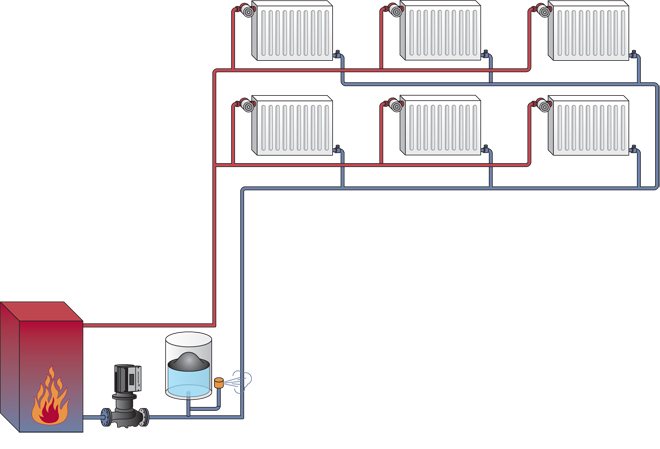
Heating with two lines
A distinctive feature of the structure of the construction of a two-pipe heating system consists of two pipe branches.
The first conducts and directs the water heated in the boiler through all the necessary devices and devices.
The other collects and removes water already cooled during operation and sends it to the heat generator.
In a single-pipe system design, water, in contrast to a two-pipe system, where it is passed through all pipes of heating devices with the same temperature indicator, undergoes a significant loss of characteristics necessary for a stable heating process on the approach to the closing part of the pipeline.
The length of pipes and the costs directly related to it increase doubly when choosing a two-pipe heating system, but this is a relatively insignificant nuance against the background of obvious advantages.
Firstly, for the creation and installation of a two-pipe construction of a heating system, pipes with a large diameter value are not required at all and, therefore, this or that obstacle will not be created in the way, as in the case of a single-pipe circuit.
All the necessary fasteners, valves and other structural details are also much smaller in size, so the difference in cost will be very imperceptible.
One of the main advantages of such a system is that it can be mounted close to each of the thermostat batteries and will significantly reduce costs and increase ease of use.
In addition, the thin ramifications of the supply and return lines also do not interfere with the integrity of the interior of the dwelling at all; moreover, they can simply be hidden behind the cladding or in the wall itself.
Having disassembled all the advantages and nuances of both heating systems on the shelves, the owners, as a rule, still prefer to choose a two-pipe system. However, it is necessary to choose one of several options for such systems, which, in the opinion of the owners themselves, will be the most functional and rational to use.
· Decrease in system performance (increase in thermal inertia).
To ensure the minimization of capital costs according to the second economic condition - the diameters of pipelines and fittings should be the smallest, but not leading, at the design flow rate of the coolant, to the appearance of hydraulic noise in the pipelines and shut-off and control valves of the heating system, which occur at values of the coolant velocity of 0.6-1 , 5 m / s depending on the value of the coefficient of local resistance.
Obviously, with the opposite direction of the above requirements for the size of the determined diameter of the pipeline, there is a region of reasonable values of the speed of the coolant movement.As the experience in the construction and operation of heating systems, as well as a comparison of capital and operating costs, shows, the optimal range of values for the speed of movement of the coolant is in the range of 0.3 ... 0.7 m / s. In this case, the specific pressure loss will be 45 ... 280 Pa / m for polymer pipelines and 60 ... 480 Pa / m for steel water and gas pipes.
Taking into account the higher cost of pipelines made of polymer materials, it is advisable to adhere to higher speeds of the coolant movement in them to prevent an increase in capital investments during construction. At the same time, operating costs (hydraulic pressure losses) in pipes made of polymeric materials will be less or remain at the same level in comparison with steel pipes due to a significantly lower value of the coefficient of hydraulic friction.
Get full text
To determine the inner diameter of the pipeline dvn
at the calculated section of the heating system with a known transported heat flow and temperature difference in the supply and return pipelines
∆tco
= 90 - 70 = 20 ° C (for two-pipe heating systems) or the flow rate of the heat carrier, it is convenient to use Table 1.
Table 1. Determination of the inner diameter of pipelines of the heating system
The further choice of pipelines for engineering life support systems, including heating, is to determine the type of pipe that, under the planned operating conditions, will provide maximum reliability and durability. Such high requirements are explained by the fact that pipelines for hot and cold water supply systems, heating, heat supply systems for ventilation and air conditioning, gas supply and other engineering systems pass through almost the entire volume of the building.
table 2

The cost of pipelines of all engineering systems in comparison with the cost of the building is less than 0.1%, and an accident or replacement of pipelines when their service life is less than the service life of the building leads to significant additional costs for cosmetic or major repairs, not to mention the possible losses in case of an accident for restoration equipment and material values in the building.
All industrial pipes used in heating systems can be divided into two large groups - metallic and non-metallic. The main distinguishing feature of metal pipes is mechanical strength, non-metal pipes are durability.
Based on the predetermined internal diameter of the pipeline, the corresponding nominal diameter is taken dy
for metal pipes or outside diameter and pipe wall thickness
dн x s
for polymer (metal-polymer) pipelines.
Different types of pipes have different mechanical, hydraulic and operational characteristics, which have a different effect on the processes of hydrodynamics and the distribution of heat flows in the heating system.
It is known that with a decrease in the hydraulic losses of friction pressure during the movement of the coolant in the pipes, the efficiency of regulating the coolant flow (heat flow) of the heating device increases due to the increase (redistribution) of the actuated available pressure on manually or automatically controlled valves, taps, valves or other fittings. In this case, they speak of an increase in the authority of the control valve. The authority of the control valve should be understood as the fraction of the pressure located in the regulated section, which is spent on overcoming the local resistance of the valve (valve) when the coolant moves.
Classification of gas pipelines
Modern gas pipelines are a whole system of complexes of structures designed to transport combustible fuel from the places of its production to consumers. Therefore, according to their intended purpose, they are:
- Trunk - for transportation over long distances from mining sites to destinations.
- Local - for collecting, distributing and supplying gas to the objects of settlements and enterprises.

Compressor stations are being built along the main routes, which are needed to maintain working pressure in the pipes and supply gas to designated points to consumers in the required volumes, calculated in advance. In them, the gas is purified, dried, compressed and cooled, and then returned to the gas pipeline under a certain pressure required for a given section of fuel passage.
Local gas pipelines located in settlements are classified:
- By type of gas - natural, liquefied hydrocarbon, mixed, etc. can be transported.
- By pressure - in different parts of the gas there is low, medium and high pressure.
- By location - outdoor (street) and indoor, aboveground and underground.
Hydraulic calculation of a 2-pipe heating system
- Hydraulic calculation of the heating system, taking into account pipelines
- An example of a hydraulic calculation for a two-pipe gravitational heating system
Why do you need a hydraulic calculation of a two-pipe heating system Each building is individual. In this regard, heating with the determination of the amount of heat will be individual. This can be done using hydraulic calculation, while the program and the calculation table can facilitate the task.
The calculation of the house heating system begins with the choice of fuel, based on the needs and characteristics of the infrastructure of the area where the house is located.
The purpose of the hydraulic calculation, the program and table of which is on the network, is as follows:
- determining the number of heating devices that are needed;
- calculation of the diameter and number of pipelines;
- determination of the possible loss of heating.
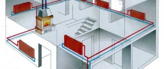
All calculations should be made according to the heating scheme with all the elements that are included in the system. A similar diagram and table must be previously compiled. To carry out a hydraulic calculation, you will need a program, an axonometric table and formulas.
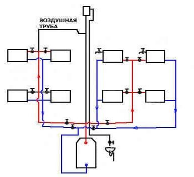
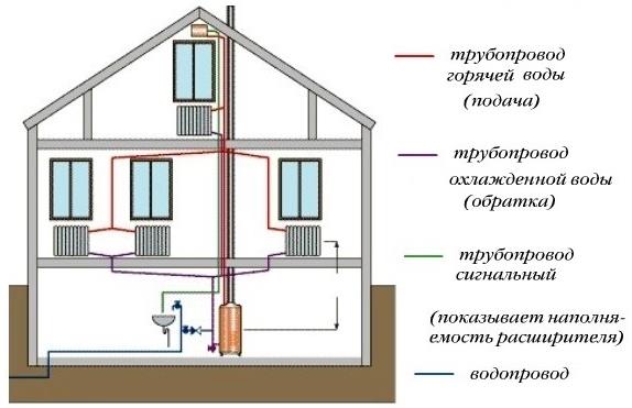
Two-pipe heating system of a private house with lower wiring.
A more loaded ring of the pipeline is taken as a design object, after which the required cross-section of the pipeline, possible pressure losses of the entire heating circuit, and the optimal surface area of the radiators are determined.
Carrying out such a calculation, for which the table and the program are used, can create a clear picture with the distribution of all the resistances in the heating circuit that exist, and also allows you to obtain accurate parameters of the temperature regime, water consumption in each part of the heating.
As a result, the hydraulic calculation should build the most optimal heating plan for your own home. Don't rely solely on your intuition. The table and calculation program will simplify the process.
Items you need:
Sequence of hydraulic calculation
1. The main circulation ring of the heating system (the most disadvantageous hydraulically located) is selected. In dead-end two-pipe systems, this is a ring passing through the lower device of the most distant and loaded riser, in single-pipe systems - through the most distant and loaded riser.
For example, in a two-pipe heating system with top wiring, the main circulation ring will pass from the substation through the main riser, the supply line, through the most distant riser, the heater of the lower floor, the return line to the substation.
In systems with passing water movement, the ring passing through the middle most loaded riser is taken as the main one.
2. The main circulation ring is divided into sections (the section is characterized by a constant water flow rate and the same diameter). The diagram shows the numbers of the sections, their lengths and heat loads. The heat load of the main sections is determined by summing up the heat loads served by these sections. Two values are used to select the pipe diameter:
a) a given water flow rate;
b) approximate specific pressure losses due to friction in the design circulation ring RWed
.
For calculation Rcp
the length of the main circulation ring and the design circulation pressure must be known.
3. The calculated circulating pressure is determined by the formula
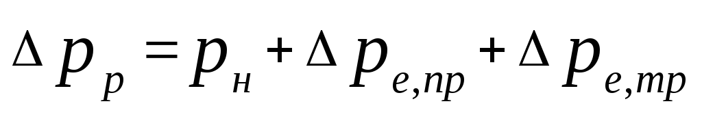
, (5.1)
Where
- pressure generated by the pump, Pa. The practice of designing a heating system has shown that it is most advisable to take the pump pressure equal to
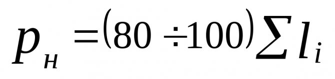
, (5.2)
Where

- the sum of the lengths of the sections of the main circulation ring;
- natural pressure arising when water is cooled in devices, Pa, can be defined as
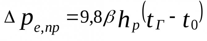
, (5.3)
Where
- distance from the center of the pump (elevator) to the center of the lower floor device, m.
Coefficient value
can be determined from Table 5.1.
Table 5.1 - Value
depending on the calculated water temperature in the heating system
(
), 0 C
, kg / (m 3 K)
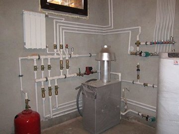
The cost-effectiveness of thermal comfort in the house is ensured by the calculation of hydraulics, its high-quality installation and proper operation. The main components of a heating system are a heat source (boiler), a heating main (pipes) and heat transfer devices (radiators). For effective heat supply, it is necessary to maintain the original parameters of the system under any load, regardless of the season.
Before the beginning hydraulic calculations are performed:
- Collection and processing of information on the object in order to:
- determining the amount of heat required;
- selection of a heating scheme.
- Thermal calculation of the heating system with justification:
- volumes of thermal energy;
- loads;
- heat loss.
If hot water heating is recognized as the best option, a hydraulic calculation is performed.
The calculations were carried out in Excel. The finished result can be seen at the end of the instructions.


Basic equations for hydraulic calculation of a gas pipeline
To calculate the movement of gas through pipes, the values of the pipe diameter, fuel consumption and head loss are taken. It is calculated depending on the nature of the movement. With laminar - calculations are performed strictly mathematically according to the formula:
Р1 - Р2 = ∆Р = (32 * μ * ω * L) / D2 kg / m2 (20), where:
- ∆Р - kgm2, head loss due to friction;
- ω - m / sec, fuel speed;
- D - m, pipeline diameter;
- L - m, pipeline length;
- μ - kg sec / m2, fluid viscosity.

In turbulent motion, it is impossible to apply accurate mathematical calculations due to the chaotic nature of the motion. Therefore, experimentally determined coefficients are used.
Calculated by the formula:
Р1 - Р2 = (λ * ω2 * L * ρ) / 2g * D (21), where:
- Р1 и Р2 - pressure at the beginning and at the end of the pipeline, kg / m2;
- λ - dimensionless coefficient of resistance;
- ω - m / sec, average gas velocity over the pipe section;
- ρ - kg / m3, fuel density;
- D - m, pipe diameter;
- g - m / sec2, acceleration of gravity.
Video: Basics of hydraulic calculation of gas pipelines
Selection of questions
- Mikhail, Lipetsk - What blades for cutting metal to use?
- Ivan, Moscow - What is the GOST of rolled metal sheet steel?
- Maxim, Tver - What racks for storage of rolled metal are better?
- Vladimir, Novosibirsk - What does ultrasonic processing of metals without the use of abrasive substances mean?
- Valery, Moscow - How to forge a knife from a bearing with your own hands?
- Stanislav, Voronezh - What equipment is used for the production of galvanized steel air ducts?
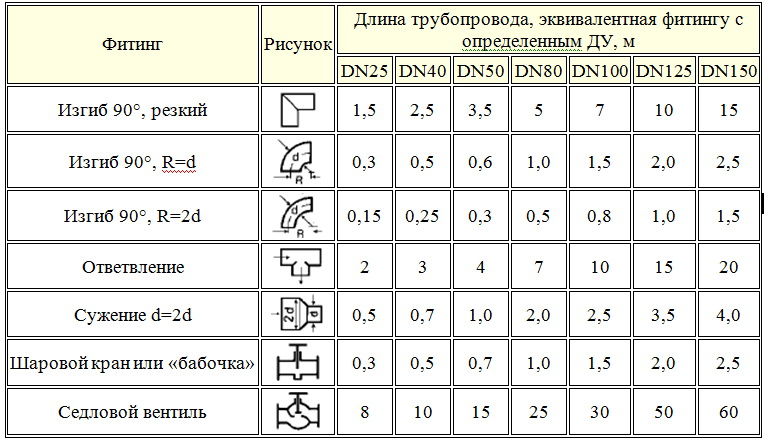
Calculation of local resistances
Local resistances arise in the pipe and fittings. The value of these indicators is influenced by:
- roughness of the inner surface of the pipe;
- the presence of places of expansion or contraction of the internal diameter of the pipeline;
- turns;
- length;
- the presence of tees, ball valves, balancing devices and their number.
The resistance is calculated for each section, which is characterized by a constant diameter and constant flow rate (in accordance with the thermal balance of the room).
Initial data for the calculation:
- the length of the calculated section - l, m;
- pipe diameter - d, mm;
- preset speed of the coolant - u, mm;
- the characteristics of the control valves provided by the manufacturer;
- coefficient of friction (depends on the pipe material), λ;
- friction losses - ∆Pl, Pa;
- coolant density (calculated) - ρ = 971.8 kg / m3;
- pipe wall thickness - dн х δ, mm;
- equivalent roughness of the pipe - ke, mm.
Pressure drop - ∆P in the network section is calculated using the Darcy-Weisbach formula.
The symbol ξ in the formula means the coefficient of local resistance.
If there is a stove in the house, it will be able to heat only a small room. The installation of heating batteries in a private house of a large area is mandatory, since otherwise the rooms remote from the stove will not be heated.
The main characteristics of the Buderus gas boiler are presented in this review.
We will tell you how to start a gas boiler in this article.
Why is it necessary to calculate the gas pipeline
Along all sections of the gas pipeline, calculations are carried out to identify places where possible resistances are likely to appear in the pipes, changing the fuel delivery rate.
If all the calculations are done correctly, then the most suitable equipment can be selected and an economical and efficient design of the entire gas system design can be created.
This will save you from unnecessary, overestimated indicators during operation and costs in construction, which could be during the planning and installation of the system without hydraulic calculation of the gas pipeline.
There is a better opportunity to select the desired size in cross-section and pipe materials for a more efficient, fast and stable supply of blue fuel to the planned points of the gas pipeline system.
The optimal operating mode of the entire gas pipeline is ensured.
Developers receive financial benefits while saving on purchases of technical equipment and building materials.
The correct calculation of the gas pipeline is made, taking into account the maximum levels of fuel consumption during periods of mass consumption. All industrial, communal, individual household needs are taken into account.
Program overview
For the convenience of calculations, amateur and professional hydraulics calculation programs are used.
The most popular is Excel.
You can use the online calculation in Excel Online, CombiMix 1.0, or the online hydraulic calculation calculator. The stationary program is selected taking into account the requirements of the project.
The main difficulty in working with such programs is the lack of knowledge of the basics of hydraulics. In some of them, there are no decoding of formulas, the features of branching of pipelines and the calculation of resistances in complex circuits are not considered.
- HERZ C.O. 3.5 - calculates using the method of specific linear pressure loss.
- DanfossCO and OvertopCO - can count natural circulation systems.
- "Flow" (Potok) - allows you to apply a calculation method with a variable (sliding) temperature difference across the risers.
It is necessary to clarify the parameters for entering data on temperature - in Kelvin / Celsius.
Calculation of the volume of water and the capacity of the expansion tank
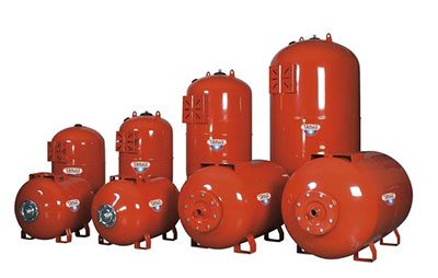
The volume of the expansion tank must be equal to 1/10 of the total volume of liquid
To calculate the performance characteristics of an expansion tank, which is mandatory for any closed-type heating system, you will need to deal with the phenomenon of an increase in the volume of liquid in it. This indicator is assessed taking into account changes in basic performance characteristics, including fluctuations in its temperature. In this case, it changes in a very wide range - from room +20 degrees and up to operating values in the range of 50-80 degrees.
It will be possible to calculate the volume of the expansion tank without unnecessary problems if you use a rough estimate that has been proven in practice. It is based on the experience of operating equipment, according to which the volume of the expansion tank is approximately one tenth of the total amount of coolant circulating in the system.
In this case, all its elements are taken into account, including heating radiators (batteries), as well as the water jacket of the boiler unit. To determine the exact value of the required indicator, you will need to take the passport of the equipment in use and find in it the items regarding the capacity of the batteries and the working tank of the boiler
After determining them, it is not difficult to find excess coolant in the system. For this, the cross-sectional area of polypropylene pipes is first calculated, and then the resulting value is multiplied by the length of the pipeline. After summing up for all branches of the heating system, the numbers for the radiators and the boiler taken from the passport are added to them. One tenth is then counted from the total.
Calculation of the parameters of the coolant
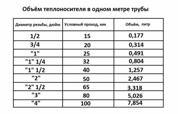
The amount of coolant in 1 m of the pipe, depending on the diameter
Calculation of the coolant is reduced to the determination of the following indicators:
- the speed of movement of water masses through the pipeline with the specified parameters;
- their average temperature;
- media consumption associated with the performance requirements of heating equipment.
The known formulas for calculating the parameters of the coolant (taking into account hydraulics) are rather complicated and inconvenient in practical use. Online calculators use a simplified approach that allows you to get a result with an acceptable error for this method.
Nevertheless, before starting the installation, it is important to worry about purchasing a pump with indicators not lower than the calculated ones. Only in this case there is confidence that the requirements for the system according to this criterion are fully met and that it is capable of heating the room to comfortable temperatures.
Types of radiators
Regarding which heating is better for a private house, the reviews of the owners are quite diverse, but as for radiators, many prefer aluminum models. The fact is that the power of the heating batteries depends on the material. They are bimetallic, cast iron and aluminum.
One section of the bimetallic radiator has a standard power of 100-180 W, cast iron - 120-160 W, and aluminum - 180-205 W.
When buying radiators, you need to find out exactly what material they are made of, since it is this indicator that is required for the correct calculation of power.
Horizontal and vertical layouts
Such a heating system is divided into horizontal and vertical schemes by the location of the pipeline connecting all devices and devices into one whole.
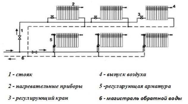
A vertical heating circuit differs from others in that in this case all the necessary devices are connected to a vertical riser.
Although its compilation will come out a little more expensive in the end, the resulting air stagnation and traffic jams will not interfere with stable operation. This solution is most suitable for apartment owners in a building with multiple floors, since all individual floors are connected separately.
A two-pipe heating system with a horizontal circuit is perfect for a one-story residential building with a relatively long length, in which it is easier and more rational to connect all available radiator compartments to a horizontal pipeline.
Both types of heating system circuits boast excellent hydraulic and temperature stability, only in the first situation, in any case, it will be necessary to calibrate the risers located vertically, and in the second - horizontal loops.
Determination of resistance
Often, engineers are faced with the calculations of heat supply systems for large facilities. Such systems require a large number of heating devices and hundreds of running meters of pipes. You can calculate the hydraulic resistance of the heating system using equations or special automated programs.
To determine the relative heat loss for adhesion in the line, the following approximate equation is used: R = 510 4 v 1.9 / d 1.32 (Pa / m). The use of this equation is justified for speeds not exceeding 1.25 m / s.
If the value of hot water consumption is known, then an approximate equation is used to find the cross-section inside the pipe: d = 0.75 √G (mm). After receiving the result, you will need to refer to a special table to get the cross-section of the conditional passage.
The most tedious and labor-intensive task will be to calculate the local resistance in pipe fittings, control valves, gate valves and heaters.
Determination of pressure losses in pipes
The pressure loss resistance in the circuit through which the coolant circulates is defined as their total value for all individual components. The latter include:
- loss in the primary circuit, denoted as ∆Plk;
- local costs of the heat carrier (∆Plm);
- pressure drop in special areas called “heat generators” under the designation ∆Ptg;
- losses inside the built-in heat exchange system ∆Pto.
After summing these values, the desired indicator is obtained, which characterizes the total hydraulic resistance of the system ∆Pco.
In addition to this generalized method, there are other methods for determining the head loss in polypropylene pipes. One of them is based on a comparison of two indicators tied to the beginning and end of the pipeline. In this case, the pressure loss can be calculated by simply subtracting its initial and final values, determined by two pressure gauges.
Another option for calculating the desired indicator is based on the use of a more complex formula that takes into account all the factors that affect the characteristics of the heat flow. The following ratio primarily takes into account the loss of fluid head due to the long length of the pipeline.
- h - liquid head loss, in the case under study measured in meters.
- λ - coefficient of hydraulic resistance (or friction), determined by other calculation methods.
- L is the total length of the served pipeline, which is measured in running meters.
- D is the internal standard size of the pipe, which determines the volume of the coolant flow.
- V is the fluid flow rate, measured in standard units (meter per second).
- The g symbol is the acceleration due to gravity, equal to 9.81 m / s2.
Pressure losses occur due to the friction of the fluid against the inner surface of the pipes
Losses caused by a high coefficient of hydraulic friction are of great interest. It depends on the roughness of the inner surfaces of the pipes. The ratios used in this case are valid only for standard round tube blanks. The final formula for finding them looks like this:
- V is the speed of movement of water masses, measured in meters / second.
- D is the inner diameter defining the free space for the movement of the coolant.
- The coefficient in the denominator indicates the kinematic viscosity of the fluid.
The last indicator refers to constant values and is found in special tables, published in large quantities on the Internet.
Hydraulic balancing
The balancing of pressure drops in the heating system is carried out by means of control and shut-off valves.
Hydraulic balancing of the system is based on:
- design load (mass flow rate of the coolant);
- dynamic resistance data from pipe manufacturers;
- the number of local resistances in the area under consideration;
- technical characteristics of fittings.
The setting characteristics - pressure drop, fastening, flow capacity - are set for each valve. According to them, the coefficients of the coolant flow into each riser are determined, and then into each device.
The pressure loss is directly proportional to the square of the coolant flow rate and is measured in kg / h, where
S is the product of the dynamic specific pressure, expressed in Pa / (kg / h), and the reduced coefficient for the local resistances of the section (ξpr).
The reduced coefficient ξпр is the sum of all local system resistances.
Calculation of the hydraulics of the heating ducts
Competently calculated hydraulics allow the correct distribution of the pipe diameter throughout the system
The hydraulic calculation of the heating system usually comes down to the selection of the diameters of the pipes laid in separate sections of the network. When conducting it, the following factors must be taken into account:
- the value of pressure and its differences in the pipeline at a given rate of circulation of the coolant;
- its estimated expense;
- typical dimensions of the pipe products used.
When calculating the first of these parameters, it is important to take into account the capacity of the pumping equipment. It should be sufficient to overcome the hydraulic resistance of the heating circuits. In this case, the total length of polypropylene pipes is of decisive importance, with an increase in which the total hydraulic resistance of the systems as a whole increases.
Based on the results of the calculation, the indicators are determined that are necessary for the subsequent installation of the heating system and meet the requirements of the current standards.
In this case, the total length of polypropylene pipes is of decisive importance, with an increase in which the total hydraulic resistance of the systems as a whole increases. Based on the results of the calculation, the indicators necessary for the subsequent installation of the heating system and meeting the requirements of the current standards are determined.
What is hydraulic calculation
This is the third stage in the process of creating a heating network. It is a system of calculations that allows you to determine:
- diameter and throughput of pipes;
- local pressure losses at sites;
- hydraulic balancing requirements;
- system-wide pressure loss;
- optimal water consumption.
According to the data obtained, the selection of pumps is carried out.
For seasonal housing, in the absence of electricity in it, a heating system with natural circulation of the coolant is suitable (link to review).
The main purpose of the hydraulic calculation is to ensure that the estimated costs for the elements of the chain match with the actual (operating) costs. The amount of coolant entering the radiators should create a thermal balance inside the house, taking into account the outside temperatures and those that are set by the user for each room according to its functional purpose (basement +5, bedroom +18, etc.).
Complex tasks - minimizing costs:
- capital - installation of pipes of optimal diameter and quality;
- operational:
- dependence of energy consumption on the hydraulic resistance of the system;
- stability and reliability;
- noiselessness.

Replacing the centralized heating mode with an individual one simplifies the calculation method
For offline mode, 4 methods are applicable hydraulic calculation of the heating system:
- by specific losses (standard calculation of pipe diameter);
- by lengths reduced to one equivalent;
- according to the characteristics of conductivity and resistance;
- comparison of dynamic pressures.
The first two methods are used with a constant temperature drop in the network.
The last two will help distribute hot water over the rings of the system if the temperature difference in the network ceases to correspond to the difference in the risers / branches.