The principle of operation and design of a thermocouple is extremely simple. This led to the popularity of this device and its widespread use in all branches of science and technology. The thermocouple is designed to measure temperatures in a wide range - from -270 to 2500 degrees Celsius. The device has been an indispensable assistant for engineers and scientists for decades. It works reliably and flawlessly, and the temperature readings are always true. A more perfect and accurate device simply does not exist. All modern devices operate on the thermocouple principle. They work in difficult conditions.
Thermocouple assignment
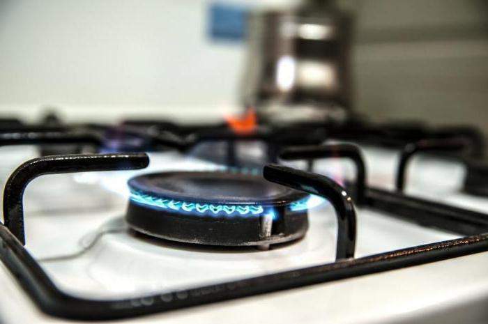
This device converts thermal energy into electrical current and allows temperature measurement. Unlike traditional mercury thermometers, it is capable of operating in conditions of both extremely low and extremely high temperatures. This feature has led to the widespread use of thermocouples in a wide variety of installations: industrial metallurgical furnaces, gas boilers, vacuum chambers for chemical heat treatment, oven for household gas stoves. The principle of operation of a thermocouple always remains unchanged and does not depend on the device in which it is mounted.
Reliable and uninterrupted operation of the thermocouple depends on the operation of the emergency shutdown system of devices in case of exceeding the permissible temperature limits. Therefore, this device must be reliable and give accurate readings so as not to endanger people's lives.
Design features
If we are more scrupulous about the process of measuring the temperature, then this procedure is carried out using a thermoelectric thermometer. The main sensitive element of this device is a thermocouple.
The measurement process itself occurs due to the creation of an electromotive force in the thermocouple. There are some features of a thermocouple device:
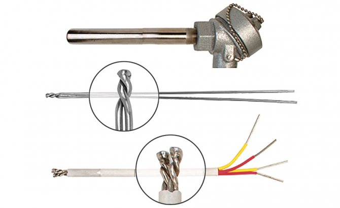
- The electrodes are connected in thermocouples to measure high temperatures at one point using electric arc welding. When measuring small indicators, such a contact is made using soldering. Special compounds in tungsten-rhenium and tungsten-molybdenum devices are carried out using tight twists without additional processing.
- The connection of the elements is carried out only in the working area, and along the rest of the length they are isolated from each other.
- The insulation method is carried out depending on the upper temperature value. With a value range from 100 to 120 ° C, any type of insulation is used, including air. Porcelain tubes or beads are used at temperatures up to 1300 ° C. If the value reaches up to 2000 ° C, then an insulating material of aluminum oxide, magnesium, beryllium and zirconium is used.
- An outer protective cover is used depending on the environment of use of the sensor in which the temperature is measured. It is made in the form of a metal or ceramic tube. This protection provides waterproofing and surface protection of the thermocouple from mechanical stress. The outer cover material must be able to withstand high temperature exposure and have excellent thermal conductivity.
It will be interesting for you Choice and features of connecting an energy meter
The design of the sensor largely depends on the conditions of its use. When creating a thermocouple, the range of measured temperatures, the state of the external environment, thermal inertia, etc. are taken into account.
How the thermocouple works
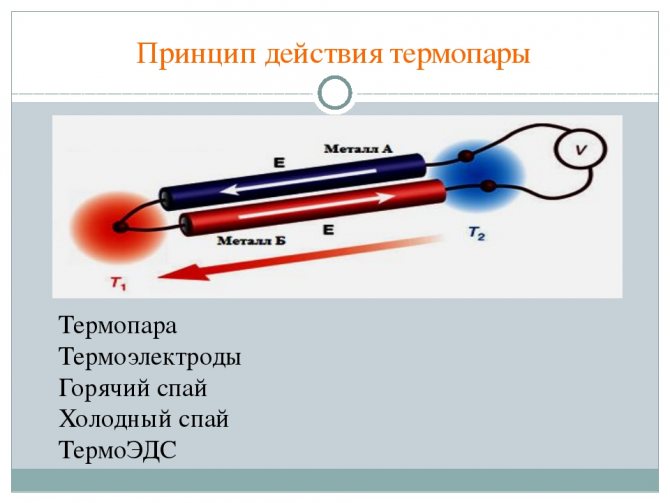
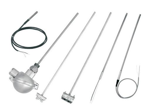
A thermocouple has three main elements. These are two conductors of electricity from different materials, as well as a protective tube.The two ends of the conductors (also called thermoelectrodes) are soldered, and the other two are connected to a potentiometer (temperature measuring device).
In simple terms, the principle of operation of a thermocouple is that the junction of thermoelectrodes is placed in an environment, the temperature of which must be measured. In accordance with the Seebeck rule, a potential difference arises on the conductors (otherwise - thermoelectricity). The higher the temperature of the medium, the more significant the potential difference is. Accordingly, the arrow of the device deviates more.
In modern measuring complexes, digital temperature indicators have replaced the mechanical device. However, the new device is far from always superior in its characteristics to the old devices dating back to Soviet times. In technical universities, and in research institutions, to this day they use potentiometers 20-30 years ago. And they exhibit amazing measurement accuracy and stability.
Design features
A thermocouple is a special device that measures temperature. The structure will consist of two dissimilar conductors, which in the future will contact each other at one or more points. When the temperature changes in one section of these conductors, then a voltage will be created. Many professionals use thermocouples quite often to control temperature in a variety of environments and to convert temperature to energy.
A commercial converter will be affordable. It will have standard connectors and can measure a wide variety of temperatures. The main difference from other temperature measuring devices is that they are self-powered and do not require an external excitation factor. The main limitation when working with this device is its accuracy.
There are also different types of thermocouples. Many fixtures are considered fully standardized. Many manufacturing companies today use electronic cold junction techniques to correct temperature changes at the device terminals. Thanks to this, they were able to significantly improve accuracy.
The use of a thermocouple is considered to be quite wide. They can be used in the following areas:
- Science.
- Industry.
- For measuring temperatures in ovens or boilers.
- Private homes or offices.
- Also, these devices are able to replace AOGV thermostats in gas heaters.
Seebeck effect
The principle of operation of a thermocouple is based on this physical phenomenon. The bottom line is this: if you connect two conductors made of different materials (sometimes semiconductors are used), then a current will circulate along such an electrical circuit.
Thus, if the junction of the conductors is heated and cooled, the potentiometer needle will oscillate. The current can also be detected by a galvanometer connected to the circuit.
In the event that the conductors are made of the same material, then the electromotive force will not arise, respectively, it will not be possible to measure the temperature.
Thermocouple connection diagram
The most common methods for connecting measuring instruments to thermocouples are the so-called simple method, as well as the differentiated one. The essence of the first method is as follows: the device (potentiometer or galvanometer) is directly connected to two conductors. With the differentiated method, not one, but both ends of the conductors are soldered, while one of the electrodes is "broken" by the measuring device.
It is impossible not to mention the so-called remote method of connecting a thermocouple. The principle of operation remains unchanged. The only difference is that extension wires are added to the circuit.For these purposes, an ordinary copper cord is not suitable, since the compensation wires must necessarily be made of the same materials as the thermocouple conductors.
Thermocouple graduation
According to GOST 8.585 and IEC 60574, thermocouple graduations have letter codes K, J, N, T, S, R, B, depending on the chemical composition of thermoelectrodes. The following table shows the designations of the thermocouple calibrations, the range in which the NSX of each type of thermocouple calibration is normalized and the color coding of the thermocouple extension wires.
| Sensor type | Wire sketch | НСХ is normalized in the temperature range | Color coding according to IEC 60584: 3-2007 | Nominal composition |
| HA (K) | From -200 | "+" Green | Chromel | |
| Up to 1370 | "-" White | Alumel | ||
| НН (N) | "+" Pink | |||
| "-" White | ||||
| LCD (J) | "+" Black | |||
| "-" White | ||||
| MK (T) | "+" Brown | |||
| "-" White | ||||
| PP (S) | ||||
| PP (R) | ||||
| ETC (B) | ||||
| XK (L) | "+" Green | |||
| "-" Yellow |
Conductor materials
The principle of operation of a thermocouple is based on the occurrence of a potential difference in conductors. Therefore, the selection of electrode materials must be approached very responsibly. The difference in the chemical and physical properties of metals is the main factor in the operation of a thermocouple, the device and principle of operation of which are based on the occurrence of an EMF of self-induction (potential difference) in the circuit.
Technically pure metals are not suitable for use as a thermocouple (with the exception of ARMKO iron). Various alloys of non-ferrous and precious metals are commonly used. Such materials have stable physical and chemical characteristics, so that temperature readings will always be accurate and objective. Stability and precision are key qualities in the organization of the experiment and the production process.
Currently, the most common thermocouples are of the following types: E, J, K.
Thermocouple features
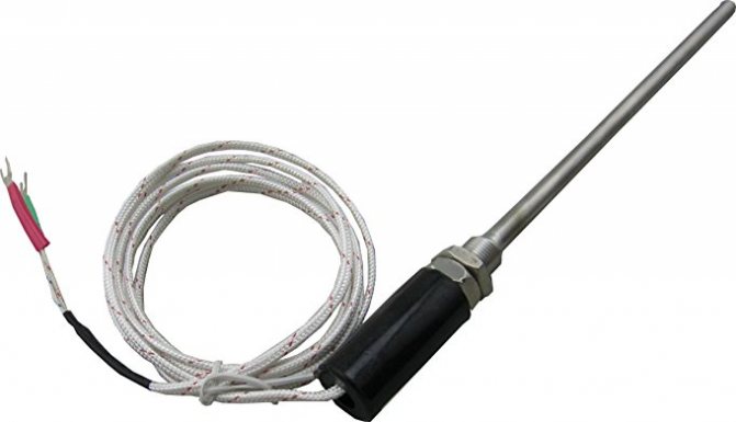
Typically, base metals are used to manufacture thermocouples. And to protect the working elements from external factors, they are placed in a tube equipped with a movable flange.
It serves as a means of fastening the structure. The thermocouple tube for a gas boiler is made of ordinary or stainless steel, and in order to exclude contact of the electrodes with each other, such means as asbestos, porcelain tubes or ceramic beads are used.
Although thermocouples are mainly made from base metals, noble materials allow them to significantly improve the measurement accuracy. Here, thermoelectric inhomogeneity is manifested to a lesser extent. In addition, they are more resistant to oxidation, and therefore such designs are highly stable. Only such devices are very expensive.
Structurally, thermocouples can be manufactured in different ways. This is also an open-frame version, where the junction of the two conductors is not closed. Such a device provides an almost instantaneous temperature measurement, and the inertness is noticeably lower.
The second version of a thermocouple for a gas stove or boiler is probes. This design has become more widespread, since it is relevant for production purposes, where it is required to protect working elements from aggressive measuring media. But in everyday life, they are also used more often than the first type.
Thermocouple type K
This is perhaps the most common and widely used type of thermocouple. A pair of chromel - aluminum works great at temperatures ranging from -200 to 1350 degrees Celsius. This type of thermocouple is highly sensitive and detects even a small jump in temperature. Thanks to this set of parameters, the thermocouple is used both in production and for scientific research. But it also has a significant drawback - the influence of the composition of the working atmosphere.So, if this type of thermocouple will work in a CO2 environment, then the thermocouple will give incorrect readings. This feature limits the use of this type of device. The scheme and principle of operation of the thermocouple remain unchanged. The only difference is in the chemical composition of the electrodes.
Types of devices
Each type of thermocouple has its own designation, and they are divided according to the generally accepted standard. Each type of electrode has its own abbreviation: TXA, TXK, TBR, etc. Converters are distributed according to the classification:
- Type E - is an alloy of chromel and constantan. The characteristic of this device is considered to be high sensitivity and performance. This is especially suitable for use at extremely low temperatures.
- J - refers to an alloy of iron and constantan. It features high sensitivity, which can reach up to 50 μV / ° C.
- Type K is considered the most popular chromel / aluminum alloy. These thermocouples can detect temperatures ranging from -200 ° C to +1350 ° C. The devices are used in circuits located in non-oxidizing and inert conditions with no signs of aging. When the devices are used in a rather acidic environment, chromel quickly corrodes and becomes unusable for measuring the temperature with a thermocouple.
- Type M - represents alloys of nickel with molybdenum or cobalt. The devices can withstand up to 1400 ° C and are used in installations operating on the principle of vacuum furnaces.
- Type N - nichrosil-nisil devices, the difference of which is considered to be resistance to oxidation. They are used to measure temperatures in the range from -270 to +1300 ° C.
It will be interesting for you Physics and consequences of electric shock
There are thermocouples made of rhodium and platinum alloys. They belong to types B, S, R and are considered the most stable devices. The disadvantages of these converters include high price and low sensitivity.
At high temperatures, devices made of rhenium and tungsten alloys are widely used. In addition, according to their purpose and operating conditions, thermocouples can be submersible and surface.
By design, the devices have a static and movable union or flange. Thermoelectric converters are widely used in computers, which are usually connected via a COM port and are designed to measure the temperature inside the case.
Checking Thermocouple Operation
If the thermocouple fails, it cannot be repaired. Theoretically, you can, of course, fix it, but whether the device will show the exact temperature after that is a big question.
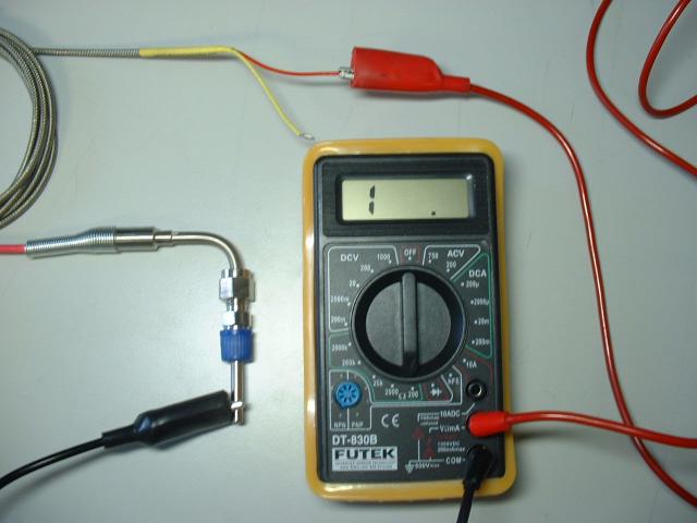
Sometimes the failure of a thermocouple is not obvious and obvious. In particular, this applies to gas water heaters. The principle of operation of a thermocouple is still the same. However, it plays a slightly different role and is intended not for visualizing temperature readings, but for valve operation. Therefore, in order to detect a malfunction of such a thermocouple, it is necessary to connect a measuring device (tester, galvanometer or potentiometer) to it and heat the junction of the thermocouple. To do this, it is not necessary to keep it over an open fire. It is enough just to squeeze it in a fist and see if the arrow of the device will deviate.
The reasons for the failure of thermocouples can be different. So, if you do not put on a special shielding device on the thermocouple placed in the vacuum chamber of the ion-plasma nitriding unit, then over time it will become more and more fragile until one of the conductors breaks. In addition, the possibility of incorrect operation of the thermocouple due to a change in the chemical composition of the electrodes is not excluded. After all, the fundamental principles of the thermocouple are violated.
Gas equipment (boilers, columns) is also equipped with thermocouples.The main cause of electrode failure is oxidative processes that develop at high temperatures.
In the case when the readings of the device are deliberately false, and during an external examination, weak clamps were not found, then the reason, most likely, lies in the failure of the control and measuring device. In this case, it must be returned for repair. If you have the appropriate qualifications, you can try to fix the problem yourself.
And in general, if the potentiometer needle or digital indicator shows at least some "signs of life", then the thermocouple is in good working order. In this case, the problem is clearly something else. And accordingly, if the device does not react in any way to obvious changes in the temperature regime, then you can safely change the thermocouple.
However, before you dismantle the thermocouple and install a new one, you need to fully make sure that it is faulty. To do this, it is enough to ring the thermocouple with an ordinary tester, or even better, measure the output voltage. Only an ordinary voltmeter is unlikely to help here. You will need a millivoltmeter or tester with the ability to select a measurement scale. After all, the potential difference is a very small value. And a standard device will not even feel it and will not fix it.
Junction thermocouple
Most thermocouples have only one junction. However, when a thermocouple is connected to an electrical circuit, another junction may form at its connection points.
Thermocouple circuit
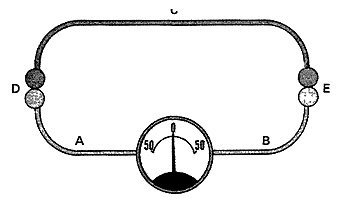
The circuit shown in the figure consists of three wires labeled A, B, and C. The wires are twisted together and labeled D and E. The junction is an extra junction that forms when a thermocouple is connected to the circuit. This junction is called the free (cold) junction of the thermocouple. Junction E is a working (hot) junction. The circuit contains a measuring device that measures the difference in voltage values across the two junctions.
The two junctions are connected in such a way that their voltage opposes each other. Thus, the same voltage value is generated on both junctions and the instrument readings will be zero. Since there is a directly proportional relationship between the temperature and the magnitude of the voltage generated by the thermocouple junction, the two junctions will generate the same voltage values when the temperature across them is the same.

Effect of heating one junction of a thermocouple
When the thermocouple junction heats up, the voltage increases in direct proportion. The flow of electrons from the heated junction flows through another junction, through the measuring device and returns back to the hot junction. The meter shows the voltage difference between the two junctions. The voltage difference between the two junctions. The voltage difference shown by the device is converted to temperature readings either using a table or directly displayed on a scale that is calibrated in degrees.
Cold junction thermocouple
The cold junction is often the point where the free ends of the thermocouple wires connect to the meter.
Since the meter in the thermocouple circuit actually measures the voltage difference between the two junctions, the cold junction voltage should be kept as constant as possible. By keeping the voltage at the cold junction constant, we ensure that a deviation in the meter reading indicates a change in temperature at the working junction.
If the temperature around the cold junction changes, then the voltage across the cold junction will also change. This will change the voltage across the cold junction. And as a consequence, the voltage difference across the two junctions will also change, which will ultimately lead to inaccurate temperature readings.
Compensating resistors are used in many thermocouples to keep the cold junction temperature constant. The resistor is in the same location as the cold junction, so the temperature affects the junction and the resistor at the same time.
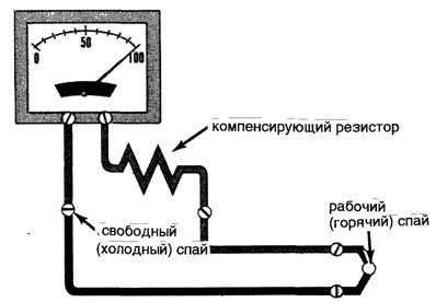
Thermocouple circuit with a compensating resistor
Thermocouple working junction (hot)
A working junction is a junction that is affected by the process whose temperature is being measured. Due to the fact that the voltage generated by the thermocouple is directly proportional to its temperature, then when the working junction heats up, it generates more voltage, and when it cools down, it generates less.
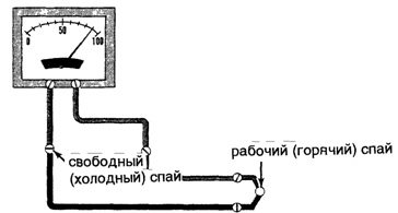
Working junction and cold junction
Thermocouple Benefits
Why have thermocouples not been replaced by more advanced and modern temperature measurement sensors over such a long history of operation? Yes, for the simple reason that until now no other device can compete with it.
First, thermocouples are relatively cheap. Although prices can fluctuate in a wide range as a result of the use of certain protective elements and surfaces, connectors and connectors.
Secondly, thermocouples are unpretentious and reliable, which allows them to be successfully operated in aggressive temperature and chemical environments. Such devices are even installed in gas boilers. The principle of operation of a thermocouple always remains the same, regardless of operating conditions. Not every other type of sensor will be able to withstand such an impact.
The technology for the manufacture and manufacture of thermocouples is simple and easy to implement in practice. Roughly speaking, it is enough just to twist or weld the ends of wires from different metal materials.
Another positive characteristic is the accuracy of the measurements and the negligible error (only 1 degree). This accuracy is more than enough for the needs of industrial production, and for scientific research.
Application of thermocouples
| This section is missing references to information sources. The information must be verifiable, otherwise it can be questioned and deleted. You can edit this article by adding links to authoritative sources. This mark is set July 31, 2012 . |
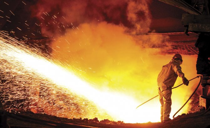
For measuring the temperature of various types of objects and media, as well as a temperature sensor in automated control systems. Tungsten-rhenium thermocouples are the highest temperature contact temperature sensors [2]. Such thermocouples are indispensable in metallurgy for controlling the temperature of molten metals.
For flame control and protection against gas contamination in gas boilers and other gas appliances (for example, household gas stoves). The current from the thermocouple, heated by the burner flame, keeps the gas valve open. In the event of a flame failure, the thermocouple current is reduced and the valve shuts off the gas supply.
In the 1920s and 1930s, thermocouples were used to power the simplest radios and other low-current devices. It is quite possible to use thermogenerators to recharge the batteries of modern low-current devices (telephones, cameras, etc.) using open fire.
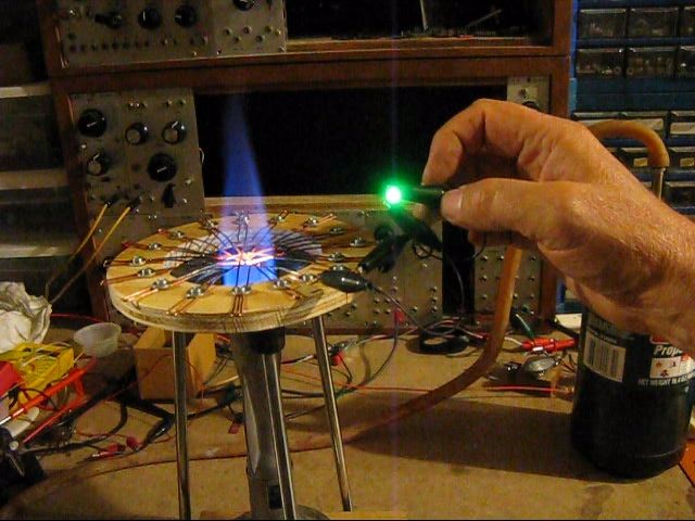
Radiation receiver
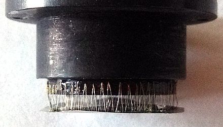
Close-up of the thermopile of the photodetector. Each of the wire angles is a thermocouple.
Historically, thermocouples represent one of the earliest thermoelectric radiation detectors [3]. The mention of this use of them dates back to the early 1830s [4]. The first receivers used single wire pairs (copper - constantan, bismuth - antimony), the hot junction was in contact with a blackened gold plate. Later designs used semiconductors.
Thermocouples can be connected in series, one after the other, forming a thermopile. In this case, hot junctions are located either along the perimeter of the receiving platform, or evenly along its surface. In the first case, individual thermocouples lie in the same plane, in the second they are parallel to each other [5].
Thermocouple Benefits
- High accuracy of temperature measurement (up to ± 0.01 ° С).
- Large temperature measuring range: from −250 ° C to +2500 ° C.
- Simplicity.
- Cheapness.
- Reliability.
disadvantages
- To obtain a high accuracy of temperature measurement (up to ± 0.01 ° С), an individual calibration of the thermocouple is required.
- The reading is influenced by the temperature of the risers, which must be corrected. In modern designs of meters based on thermocouples, the temperature of the block of cold junctions is measured using a built-in thermistor or semiconductor sensor and automatic correction to the measured TEMF is used.
- Peltier effect (at the time of taking readings, it is necessary to exclude the flow of current through the thermocouple, since the current flowing through it cools the hot junction and heats the cold one).
- The temperature dependence of the thermopower is substantially nonlinear. This creates difficulties in the design of secondary signal converters.
- The appearance of thermoelectric inhomogeneity as a result of sharp temperature changes, mechanical stresses, corrosion and chemical processes in conductors leads to a change in the calibration characteristic and errors up to 5 K.
- Long thermocouple and extension wires can create an “antenna” effect for existing electromagnetic fields.
Disadvantages of Thermocouple
There are not many disadvantages of a thermocouple, especially when compared with its closest competitors (temperature sensors of other types), but still they are, and it would be unfair to keep silent about them.
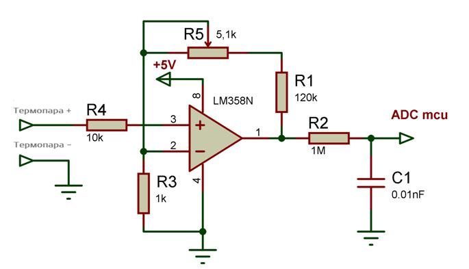
So, the potential difference is measured in millivolts. Therefore, it is necessary to use very sensitive potentiometers. And if we take into account that metering devices can not always be placed in the immediate vicinity of the place of collection of experimental data, then some amplifiers have to be used. This causes a number of inconveniences and leads to unnecessary costs in the organization and preparation of production.