Objectives and goals
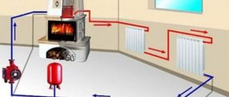
Modern boiler automation systems are able to guarantee trouble-free and efficient operation of equipment without direct operator intervention. Human functions are reduced to online monitoring of the health and parameters of the entire complex of devices. Boiler house automation solves the following tasks:
- Automatic start and stop of boilers.
- Boiler output regulation (cascade control) according to the specified primary settings.
- Booster pump control, control of the coolant levels in the working and consumer circuits.
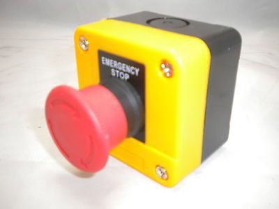
- Emergency stop and activation of signaling devices in case of system operating values outside the set limits.

Automation object
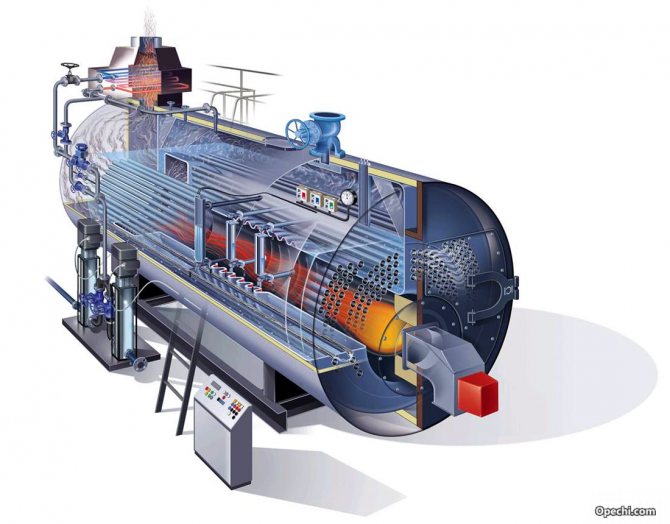
Boiler equipment as an object of regulation is a complex dynamic system with many interconnected input and output parameters. The automation of boiler houses is complicated by the fact that the rates of technological processes are very high in steam units. The main regulated values include:
- flow rate and pressure of the heat carrier (water or steam);
- discharge in the firebox;
- the level in the feed tank;
- in recent years, increased environmental requirements have been imposed on the quality of the prepared fuel mixture and, as a result, on the temperature and composition of the flue gases.
Automatic regulation of marine auxiliary boilers
General information
If fire-tube boilers with a high storage capacity are to some extent amenable to manual control, then in modern water-tube boilers, reacting to very small deviations in modes, such regulation is very difficult and leads to large heat losses.
During the operation of the boiler, it is very important to maintain the nominal values of such quality parameters as steam pressure, water level in the boiler, fuel pressure and temperature, excess air ratio, etc. air firebox. An excess of water in the boiler reduces steam production, leads to the throwing of water into the steam line, and the loss of water leads to burnout of pipes, breakdown of seams, the appearance of cracks, etc. The use of automatic means for regulating auxiliary boilers, along with the general advantages of automation, eliminates the listed disadvantages of manual regulation ...
The following main parameters of the boiler are subject to regulation: water level; steam pressure; the air-fuel ratio, i.e. the ratio between the amount of fuel burned and air.
Water level regulation with direct acting regulator
The control circuit is shown in Fig. 114. The controlled value is the level of the liquid in the tank, which depends on the disturbing effect (the inflow of liquid into the tank). The impact is recorded by the measuring element (float) and is transmitted through the actuator (organ) to the regulating organ (valve). The latter covers or opens the drain line. Such a control system does not require an external source of energy to move the regulating body (valve). Regulators of such a system are called direct acting or direct acting regulators.
Direct-acting regulators have reduced sensitivity. They are used when special accuracy is not required.The regulator must be located near the object of regulation. They are mainly used in the heating system.
If the efforts of the measuring element (sensor) are insufficient, then to amplify the pulse developed by the sensor, a special amplifying organ or amplifier is introduced into the automatic control system, using various types of auxiliary energy. In this case, the regulator will be referred to as an indirect regulator.
Water level regulation with an indirect regulator
A schematic diagram of the automatic power supply system of a boiler with a thermohydraulic water level regulator is shown in Fig. 115.
Thermohydraulic level control is carried out by the operation of the measuring element (bellows) and the regulating element (valve), as well as the thermohydraulic sensing element and the switch of the reserve pump. A bellows is a harmonic-shaped elastic cylinder with a blind bottom. With a change in pressure in the thermo-hydraulic sensing element, the bottom of the bellows, bending to one side or the other, through the system of intermediate elements acts on the regulating body. The thermo-hydraulic element (sensor) consists of two tubes inserted into one another. The ends of the outer tube are hermetically connected to the inner tube so that an annular space is formed between them, which is filled with distilled water. The inner tube is connected to the steam and water space of the boiler, and the outer tube is connected to the cavity of the bellows. The axis of the sensing element is set with some inclination to the water level in the boiler, therefore, with a slight change in the water level in the boiler, the level in the inner tube of the sensor changes significantly. As the water level falls, the inner tube is filled with steam, which gives off heat to distilled water in the annular space, in the latter the water evaporates, which leads to an increase in pressure and bending of the bellows bottom. At the moment the water level in the boiler rises, distilled water vapors condense, the pressure absorbing the bellows changes again. For better heat dissipation into the environment, the outer tube of the sensing element (sensor) is ribbed.
The principle of operation of this system is as follows. With a decrease in the water level in the boiler, the pressure on the bellows of the measuring element increases and the control valve is closed. The discharge of water from the boiler feed system into the warm box is partially or completely stopped and the amount of water supplied to the boiler by the electric feed pump increases. If the water level in the boiler drops despite the operation of the electric feed pump, the backup steam pump is automatically activated. The operation of the standby feed pump is controlled by the activation regulator. The device of the switching regulator is shown in Fig. 116. Under the action of a certain pressure on the bellows (Fig. 116, a), valve 12 opens and steam from the boiler enters the spool box of the feed pump. To increase the sensitivity of the pump activation regulator, instead of the stem seal, a second bellows 8 is mounted in its body. The active area of this bellows and the flow area of the valve 12 are equal, therefore, significant efforts are not required to move the valve. The regulator is adjusted by changing the spring force using a nut. Air during adjustment is removed through the plug. Manual control of the regulator can be done with screw 7 and angle lever 5. To protect the control valve from possible clogging, a filter is included in the line. Condensation builds up in the steam cylinders when the steam piston pump is inactive. The pump is purged by taps 3 and 4 (see Fig. 115) installed in the cavities of the steam cylinders of the pump.At the first moment of operation of the regulator, the steam pressure on the pump will be insufficient for its operation, but the pressure in the cylinder cavity will provide valve 16 lift (see Fig. 116, b) and condensate through hole 15 will be removed from the cylinder into the atmosphere. When the backup pump is operating, the rubber membrane 13 will bend under water pressure and, acting on the valve through the rod 14, will stop the purging of the cylinders. The considered indirect water level regulator is significantly perfect, providing sufficient control accuracy. Higher reliability of regulation is provided by the regulators of the TsNII im. acad. A. I. Krylova.
Hydraulic power supply regulator of the Central Research Institute named after academician Krylov
Schematic diagram of the power supply regulator of the TsNII im. acad. Krylov is shown in Fig. 117. The sensor of the measuring element (condensation vessel) 1 is connected by pipelines with the water and steam space of the boiler and with the lower and upper cavities of the measuring element 2. The used working medium (feed water) in the regulator is cleaned by a filter. When the regulator is turned on, a force equal to the weight of the liquid column, directed from bottom to top and balanced by weights 9 and 10 acts on the membrane. in turn, through a system of levers, it controls the amplifier and the operation of the electrically driven feed pump, and also switches on the alarm and protection circuit at the appropriate time.
The reinforcing body of the jet type is connected by the boiler feed system with the cavities of the piston servo motor. To increase the speed of the water, and, consequently, to increase its kinetic energy, there is a nozzle in the amplifier housing. If the swinging pipe turns, water flows through the nozzle into the upper or lower cavity of the servomotor, moving the piston. The piston through a system of levers changes the size of the flow area of the feed control valve.
Hard feedback restores the balance of the amplifier, that is, it sets the swinging tube of the amplifier to the nearest middle position, in which the working water is discharged through the hole in the amplifier housing into a warm box. The supply control valve 5 is held by the servomotor in the position at which the operating level in the boiler is ensured.
The control valve can be opened and closed manually with the handle 13. In addition to the indirect hydraulic water level controllers discussed above, auxiliary boilers can be equipped with pneumatic and electromechanical power controllers. Electromechanical regulators are most widely used.
Electromechanical power regulator
A diagram of an electrical power regulator with a diaphragm measuring element is shown in Fig. 118. With a change in the water level in the boiler, the thermohydraulic sensing element exerts a different impulse pressure on the membrane (not shown in the figure). The force of the diaphragm transmitted through the needle 4 to the lever 7, at a normal water level, is balanced by the feedback spring 6.
In this case, the electric feed pump operates normally. When the water level in the boiler decreases, the hydrostatic pressure on the membrane increases, the needle turns the lever, the middle contact 2 closes with contact 3 and, through the corresponding electric relay, increases the performance of the electric pump.
When the water level rises, the middle contact closes with contact 1 and the electric relay reduces the performance of the electric pump, and, if necessary, turns it off. Pressing the feedback spring is regulated by turning the eccentric roller 5, which is connected to a reversible electric motor (servomotor) by means of a reducer.Depending on which contact contact 2 closes, the rotation of the servomotor rotates the eccentric roller 5 in such a way that the feedback spring would facilitate the return of contact 2 to the middle position through the lever 7. Regulators of this type provide a very high accuracy in regulating the water level in the boiler.
Steam pressure control
In auxiliary boilers, the steam pressure is regulated by changing the amount of fuel burned and air supply, i.e. by regulating the combustion process.
By design, the combustion process controllers are divided into mechanical, hydraulic, pneumatic and electrical. Mechanical regulators have a large number of mechanical transmissions, insufficient sensitivity and are not used in ship boiler installations. Pneumatic regulators have found little use due to the laboriousness of their adjustment due to the large number of regulating bodies. The principle of maintaining a constant pressure by hydraulic combustion control is shown in the diagram in Fig. 119.
With a slight increase in the vapor pressure in the impulse pipeline, the bellows of the measuring element bends, the needle 6 acts on the two-arm lever and the swinging tube of the jet amplifier is displaced towards the axis of the left receiving nozzle. In the lower cavity of the servomotor, pressure increases, moving the piston 10 to the upper position and, through a system of levers, closes valve 1.
At the same time, using the lever 9, the air supply is reduced by the air register (the air register is not shown in Fig. 119). With a slight decrease in steam pressure in the boiler, the reverse process occurs. In case of failure of the regulator, the combustion can be controlled manually with knob 8. In this case, the servo motor and the amplifier are disconnected. Such a scheme for regulating the combustion mode, in comparison with conventional maintenance, allows you to obtain significant fuel savings, since the amount of fuel burned is mutually consistent with the amount of air entering the furnace.
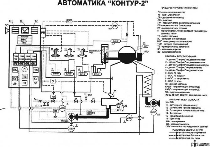
Control devices used in automatic control systems
Mercury thermometers, which can measure temperatures from 0 to + 500 ° C, have little mechanical strength and their readings often lag behind actual temperature changes; they are rarely used in automatic control systems.
Liquid or gas gauge thermometers shown in fig. 120 do not have these drawbacks. Thermal balloon 1 of a liquid thermometer (Fig. 120, a) is filled with an easily evaporating liquid (acetone, chloromethyl, or an inert gas) and communicates with a conventional pressure gauge 3 with the help of a capillary tube 2, the scale of which is graduated in ° C.
The pressure gauge is installed on the control panel, and the bulb is placed in an environment whose temperature is changing. With an increase in the temperature of the medium, the pressure in the cylinder increases, and the arrow, turning through a certain angle, shows the true temperature.
The temperature in the furnace and flue gases is usually measured with a thermoelectric thermometer (thermocouple), shown in Fig. 120, b.
A thermocouple consists of two wires made of different materials, placed in a steel case filled with insulating material. The ends of the wires are soldered. When the temperature of the medium changes in dissimilar wires, microcurrents arise, leading to a change in the position of the arrow of the galvanometer 3 connected to the free ends of the wires. The galvanometer scale is graduated in ° C.
Signaling and protection of systems for automatic regulation of the operation of auxiliary boilers is carried out using the applied relay and other devices.
A thermal relay connected through electrical devices with a regulating body and devices for sound and light alarms is shown in Fig. 121, a. The thermostat is a sensor for the limiting temperature of water or steam in boilers. Inside the brass tube 3, two flat invar (iron-nickel alloy) springs 5 with contacts 4 are installed. a certain gap is set. The thermostat body is screwed into the fitting installed on the controlled object. Due to the fact that Invar has a significantly lower coefficient of linear expansion, with an increase in the temperature of the medium, the spring will not stretch until the gap between it and the shoulder of the axis 6 is selected. the impulse will be transmitted to the electrical circuit.
In automatic control systems of boilers, a photo relay is used as a combustion sensor. The photo relay is shown in Fig. 121, b.
The principle of operation of the photo relay is to change the electrical resistance of the photocell 14 when the degree of its illumination changes. Glasses 16, inserted into the relay housing from the side of the firebox, are a means of protecting the photoresistor. The body of the photoelectric relay 12 is attached to the front of the boiler with a sleeve 15. A cable is connected to the semiconductor photoresistor 14 from the power network through a sealing gland 17 and an insulating panel 13.
The circuit of the fuel ignition system is broken when the luminous flux of the combustion flame reduces the resistance of the semiconductor. When the flame breaks, the resistance of the conductor increases sharply, the protection circuit turns on (the solenoid valves on the fuel and supply systems of the boiler are closed) and the alarm circuit is turned on.
In electrical control systems for marine auxiliary boilers, an electromagnetic relay is most commonly used.
The electromagnetic relay is shown in fig. 121, v. In the case of the passage of current through the coil 8, the core 10 attracts the armature 9 and closes the contact 11. In this case, the control object will turn on. When the coil is de-energized, the feedback spring 7 opens the contact, i.e. acts on the controlled object. Such a relay has normally open contacts, i.e. contacts that are open in the absence of current.
Similar articles
- Marine auxiliary boiler fittings
- Combined heat recovery boilers
- Marine recovery boilers, purpose, device
- Shukhov system vertical combined boiler
- Auxiliary double-circuit boiler
- Auxiliary water tube boilers
- Auxiliary fire tube boilers
- Classification of marine auxiliary boilers
- The main indicators characterizing the boiler
- The purpose of the auxiliary boiler plant and its diagram
Rating 0.00 (0 Votes)
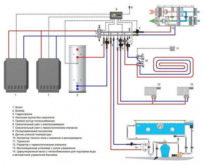
Automation levels
The degree of automation is set when designing a boiler room or when overhauling / replacing equipment. It can range from manual control based on instrumentation readings to fully automatic control based on weather-dependent algorithms. The level of automation is primarily determined by the purpose, power and functional features of the equipment operation.
Modern automation of the boiler house operation implies an integrated approach - the control and regulation subsystems of individual technological processes are combined into a single network with functional group control.
4.1. Basic principles of boiler automation
Reliable, economical and safe operation of a boiler house with a minimum number of maintenance personnel can be carried out only in the presence of thermal control, automatic regulation and control of technological processes, signaling and equipment protection [8].
The main decisions on the automation of boiler houses are made in the process of developing automation schemes (functional diagrams). Automation schemes are developed following the design of heat engineering schemes and decision-making on the choice of the main and auxiliary equipment of the boiler room, its mechanization and heat engineering communications. The main equipment includes a boiler unit, smoke exhausters and fans, and the auxiliary equipment includes a pumping and deaeration unit, a chemical water treatment plant, a heating unit, a condensate pumping station, a gas distribution station, a fuel oil (coal) warehouse and a fuel supply.
The scope of automation is taken in accordance with SNiP II-35-76 (section 15 - "Automation") and the requirements of manufacturers of thermal mechanical equipment.
The level of automation of boiler houses depends on the following main technical factors:
- type of boiler (steam, hot water, combined - steam and water);
- the design of the boiler and its equipment (drum, direct-flow, cast-iron sectional pressurized, etc.), the type of draft, etc .; the type of fuel (solid, liquid, gaseous, combined - gas-oil, pulverized) and the type of fuel-burning device (TSU);
- the nature of heat loads (industrial, heating, individual, etc.);
- the number of boilers in the boiler room.
When drawing up the automation scheme, the main subsystems of automatic control, technological protection, remote control, heat engineering control, technological blocking and signaling are provided.
General structure
Boiler house automation is based on a two-level control scheme. The lower (field) level includes devices of local automation based on programmable microcontrollers that implement technical protection and blocking, adjustment and change of parameters, primary converters of physical quantities. This also includes equipment for converting, encoding and transmitting information data.
The upper level can be presented in the form of a graphic terminal built into the control cabinet or an automated operator's workstation based on a personal computer. All information from the low-level microcontrollers and system sensors is displayed here, and operational commands, adjustments and settings are entered. In addition to dispatching the process, the tasks of optimization of modes, diagnostics of technical conditions, analysis of economic indicators, archiving and data storage are solved. If necessary, the information is transferred to the general enterprise management system (MRP / ERP) or settlement.
Distinctive features
Technological protection. The system of automatic input and output of protections ensures the possibility of normal operation of technological equipment in all operating modes, including starting modes, without personnel intervention in the operation of the protections. The interface part of the subsystem of technological protections and interlocks is made in a form that is convenient for understanding the algorithm and allows you to quickly and efficiently understand the reasons for the action of protection or blocking.
Technological protections include:
- automatic and authorized manual activation / deactivation,
- authorized adjustment of protection settings
- control of action and registration of the root cause of activation
- formation of protocols of emergency situations, registering changes in analog and discrete parameters before and after the accident.
Automated subsystem for boiler burner control (SAUG). A feature of the subsystem is its deep integration with PTK KRUG-2000... SAUG allows you to automatically check the tightness of gas fittings and ignite burners, as well as implement the requirements of regulatory documents for the safe operation of gas equipment of boiler units. For more details about the subsystem, see the page Boiler unit burner ignition control subsystem (SAUG).
Automatic regulation. Automatic controllers provide modern system engineering solutions that ensure their stable operation in the range of permissible loads, such as:
- implementation of multi-loop control circuits and control circuits with correcting signals
- algorithms for switching from one type of fuel to another
- the ability to change adjustable parameters and actuators
- correction of the setting for the combustion air regulator in accordance with the oxygen content, consumption and type of fuel burned
- logic control circuits and technological interlocks, ensuring the safety of the regulators in normal and transient modes
- various types of balancing
- fault signaling
- handling invalid parameters
- tracking modes, etc.
Control of executive mechanisms (MI). MI control is carried out taking into account the priorities of the incoming signals. Process protection signals have the highest priority. The next in priority are the commands of logical tasks (interlocks of normal operation). Then - operator control commands. Remote control of the MI is carried out from video frames on which the corresponding equipment is displayed, using virtual control panels, a manipulator of the "mouse" type or a functional keyboard. The functions of group control of the IM are provided.
Boiler equipment automation
The modern market is widely represented both by individual devices and devices, and by domestic and imported automatic sets for steam and hot water boilers. Automation tools include:
- ignition control equipment and the presence of a flame, starting and controlling the process of fuel combustion in the combustion chamber of the boiler unit;
- specialized sensors (draft gauges, temperature and pressure sensors, gas analyzers, etc.);
- actuators (solenoid valves, relays, servo drives, frequency converters);
- control panels for boilers and general boiler equipment (consoles, sensor mimic diagrams);
- switching cabinets, communication and power supply lines.
When choosing technical means of control and monitoring, the most close attention should be paid to safety automation, which excludes the occurrence of abnormal and emergency situations.
The principle of operation of the boiler automation
The principle of operation of the gas boiler automation is simple. It is worth considering that both foreign and Russian manufacturers use the same operating principle in their products, although the devices may be structurally different. The simplest and most reliable boiler automation is considered to be automatic gas valves from Italian manufacturers.
So, the principle of operation of the boiler automation is as follows:
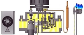
- All structural elements are placed in one housing, to which gas pipelines are connected. In addition, a capillary tube from the thrust and temperature sensors (thermocouples), a gas supply line for the igniter and a cable from the piezoelectric element are connected to the device.
- Inside there is a shut-off solenoid valve, whose normal state is "closed", as well as a gas pressure regulator and a spring-loaded valve. Any automatic gas boiler equipped with a combined gas valve is started manually.Initially, the fuel path is closed off by a solenoid valve. While holding the washer, we press the button of the piezoelectric device and ignite the igniter, which heats the thermosensitive element for 30 seconds. It generates a voltage that keeps the solenoid valve open, after which the adjusting washer can be released.
- Then we turn the washer to the required division and thereby open access to the fuel to the burner, which is independently ignited from the igniter. Since the automation of gas boilers is designed to maintain the set temperature of the coolant, human intervention is no longer required. Here the principle is as follows: the medium in the capillary system expands when heated and acts on the spring valve, closing it when a high temperature is reached.
- The burner is extinguished until the thermocouple cools down and the gas supply is resumed.
The principle of operation of the gas boiler automation is simple. It is worth considering that both foreign and Russian manufacturers use the same operating principle in their products, although the devices may be structurally different. The simplest and most reliable boiler automation is considered to be automatic gas valves from Italian manufacturers.
Subsystems and functions
Any boiler room automation scheme includes control, regulation and protection subsystems. Regulation is carried out by maintaining the optimal combustion mode by setting the vacuum in the furnace, the primary air flow rate and the parameters of the coolant (temperature, pressure, flow rate). The control subsystem outputs actual data on the operation of the equipment to the human-machine interface. Protection devices guarantee the prevention of emergency situations in case of violation of normal operating conditions, the supply of a light, sound signal or shutdown of the boiler units with the fixation of the cause (on a graphic board, mnemonic diagram, board).
Communication protocols
Automation of boiler plants based on microcontrollers minimizes the use of relay switching and control power lines in the functional circuit. An industrial network with a specific interface and data transfer protocol is used to communicate the upper and lower levels of the ACS, transfer information between sensors and controllers, and transmit commands to executive devices. The most widely used standards are Modbus and Profibus. They are compatible with the bulk of equipment used to automate heat supply facilities. They are distinguished by high indicators of the reliability of information transfer, simple and understandable principles of operation.
3.2.1. Thermal diagrams of boiler rooms with hot water boilers and the basics of their calculation
To reduce the consumption of feed water during continuous blowdown, two-stage evaporation is used.
Water from the return line of heating networks goes to the network pumps.
To equalize the mode of hot water preparation, as well as to limit and equalize the pressure in hot and cold water supply systems in heating boiler rooms, it is envisaged to install storage tanks. Water is supplied to them by make-up pumps from the tank, which compensates for losses in the networks.
The rear firewall in the upper part of the firebox is sparse and forms the so-called scallop. In this case, the values of the throughput are related as 0.5: 0.7: 1: 2. They are used as shut-off valves for passage diameters up to mm.
Instead of the throttle diaphragm shown in the diagram, it is desirable to make the transition of the pipeline to a smaller diameter. Water heating networks are of two types: closed and open.
Thermal diagrams can be basic, detailed and working or installation. Depending on the type of heat carrier, boiler rooms are divided into hot water, steam and steam water heating.The screen pipes of the furnace are in a zone of high temperatures, therefore, it is necessary to intensively remove heat using the water circulating in these pipes. The quality of water preparation for replenishment of an open heating system should be significantly higher than the quality of water for replenishment of a closed system, since the same requirements are imposed on hot water supply as to drinking tap water. The network circulating pump installed on the return line ensures the flow of feed water to the boiler and then to the heat supply system.
Boiler plant diagrams
The scheme of a steam-heating boiler house consists of two circuits: 1 for generating steam and 2 for generating hot water. Construction of boiler houses with steam and hot water boilers is economically feasible only if the total heating capacity of the boiler house is more than 50 MW. The survivability of the boiler room can be significantly increased if the control is divided. However, part of the ash in the form of liquid and pasty slag, together with unburned fuel particles, the flue gases are captured and removed from the combustion chamber. The amount of mixed water is regulated by valve 5, depending on the magnitude of the heat load.
Thermal schemes of hot water heating boiler houses can be divided according to technology into two types and several subspecies. One deaerator is provided for preparation of boiler feed water and heating network feed water. The vacuum in the deaerator is maintained by sucking the air-vapor mixture from the deaerator column using a water-jet ejector. The pretreatment of water is called water treatment, and the treated water suitable for feeding the boilers is called nutritional water. The PID controller maintains a constant water temperature at the outlets of high-speed water heaters by smoothly changing the heating water temperature. ✅ Boiler room in a private house of 180 sq.m. And a warm water floor.
Energy saving and social effects of automation
Automation of boiler houses completely eliminates the possibility of accidents with the destruction of capital structures, the death of service personnel. ACS is able to ensure the normal functioning of equipment around the clock, to minimize the influence of the human factor.
In the light of the continuous growth of prices for fuel resources, the energy-saving effect of automation is of no small importance. Saving natural gas, reaching up to 25% during the heating season, is ensured by:
- optimal ratio "gas / air" in the fuel mixture at all operating modes of the boiler room, correction for the level of oxygen content in combustion products;
- the ability to customize not only boilers, but also gas burners;
- regulation not only by the temperature and pressure of the coolant at the inlet and outlet of the boilers, but also taking into account the environmental parameters (weather-dependent technologies).
In addition, automation allows you to implement an energy-efficient algorithm for heating non-residential premises or buildings that are not used on weekends and holidays.
Boiler plant diagrams
The steam-water mixture removed from the deaerator head passes through a heat exchanger - vapor cooler.
Vacuum deaerators are often installed in boiler rooms with hot water boilers. Draw up a heat supply scheme. From the feed water deaerator, the feed pump feeds water to the steam boilers and for injection into the PRC.
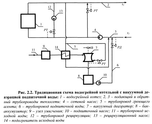
If scale forms on the inner walls of the wall tubes, it hinders the transfer of heat from the incandescent combustion products to water or steam and can lead to overheating of the metal and rupture of the tubes under the influence of internal pressure. Since the water consumption in an open system is uneven in time, in order to align the daily schedule of loads on hot water supply and reduce the estimated capacity of boilers and water treatment equipment, it is necessary to install deaerated hot water storage tanks.Recirculation is necessary to heat water at the inlet to steel boilers to a temperature higher than the dew point temperature, the values of which depend on the type of fuel, as well as to maintain a constant water flow through the boilers.
With periodic blowdowns, water containing a significant amount of sludge is sent to a periodic blowdown expander bubbler, from where the generated steam is discharged into the atmosphere, and the rest of the water with sludge is discharged into the sewer. When calculating the thermal diagram of a water-heating boiler house, when there are no phase transformations of the heated and cooled water media, the heat balance equation in general form can be written as follows, 3. Such conditions sometimes dictate the need to use an increased number of pumps in the thermal circuits of boiler houses - winter and summer network pumps, pumping, recirculating and make-up also winter and summer.
Alternative renewable sources such as sun, wind, water, rainwater and biomass account for only a small share of total energy consumption, despite the fact that it is rapidly increasing. This minimizes fur. If the water pressure is reduced to 0.03 MPa, then at this pressure the water will boil at a temperature of 68.7 ° C. In them, steam gives off heat to the feed water, condenses and condensate is poured into the general flow of feed water.
General design considerations
Thermal circuits in which the water flow through the boiler changes. Further, the heated network water flows through pipelines to the consumer. In general, a boiler plant is a combination of a boiler, boilers and equipment, including the following devices.
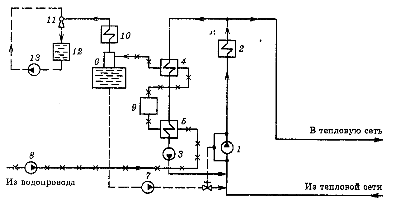
If the steam-heating boiler house serves open water networks, the thermal circuit provides for the installation of two deaerators - for feed and make-up water. The network circulating pump installed on the return line ensures the flow of feed water to the boiler and then to the heat supply system. Date added:; views:;. Schematic diagram of a boiler room with steam boilers supplying steam and hot water 1 - boilers; 2 - ROU, 3 - control valve, 4 - steam-water heat exchanger, 5 - condensate drain, 6 - mains pump, 7 - filter, 8 - make-up regulator, 9 - deaerator, 10 - feed pump, 11 - chemical water treatment devices, 12 - make-up pump Steam-water boilers, also called mixed ones, are equipped with the above types of steam and hot water boilers or combined steam-and-water boilers, for example, of the KTK type and are designed to generate steam for technological needs and hot water to provide loads for heating, ventilation and hot air. Strange boiler room scheme